Downwind aerogenerator gyrodamping and locking mechanism

A wind turbine and stop mechanism technology, applied to wind turbines, wind turbines, wind turbine components, etc. that are in line with the wind direction, can solve problems such as low efficiency, easy wear of parts, and easy swing of the wind turbine host, and achieve Improved work efficiency, simple operation, and reduced wear

Inactive Publication Date: 2009-06-03
ZHEJIANG HUAYING WIND POWER GENERATOR
View PDF0 Cites 0 Cited by
  • Summary
  • Abstract
  • Description
  • Claims
  • Application Information

AI Technical Summary

Problems solved by technology

[0002] In the existing downwind wind turbines, since the wind rotor is located on the downwind side of the main engine and the tower pole, the main engine of the wind turbine tends to sway easily during operation due to the influence of factors such as wind changes and the tower shadow effect, resulting in unstable power output of the generator. Stable, low efficiency, and parts such as slewing bearings are easy to wear due to frequent work

Method used


Image

  • Downwind aerogenerator gyrodamping and locking mechanism
  • Downwind aerogenerator gyrodamping and locking mechanism
  • Downwind aerogenerator gyrodamping and locking mechanism

Examples


Embodiment 1

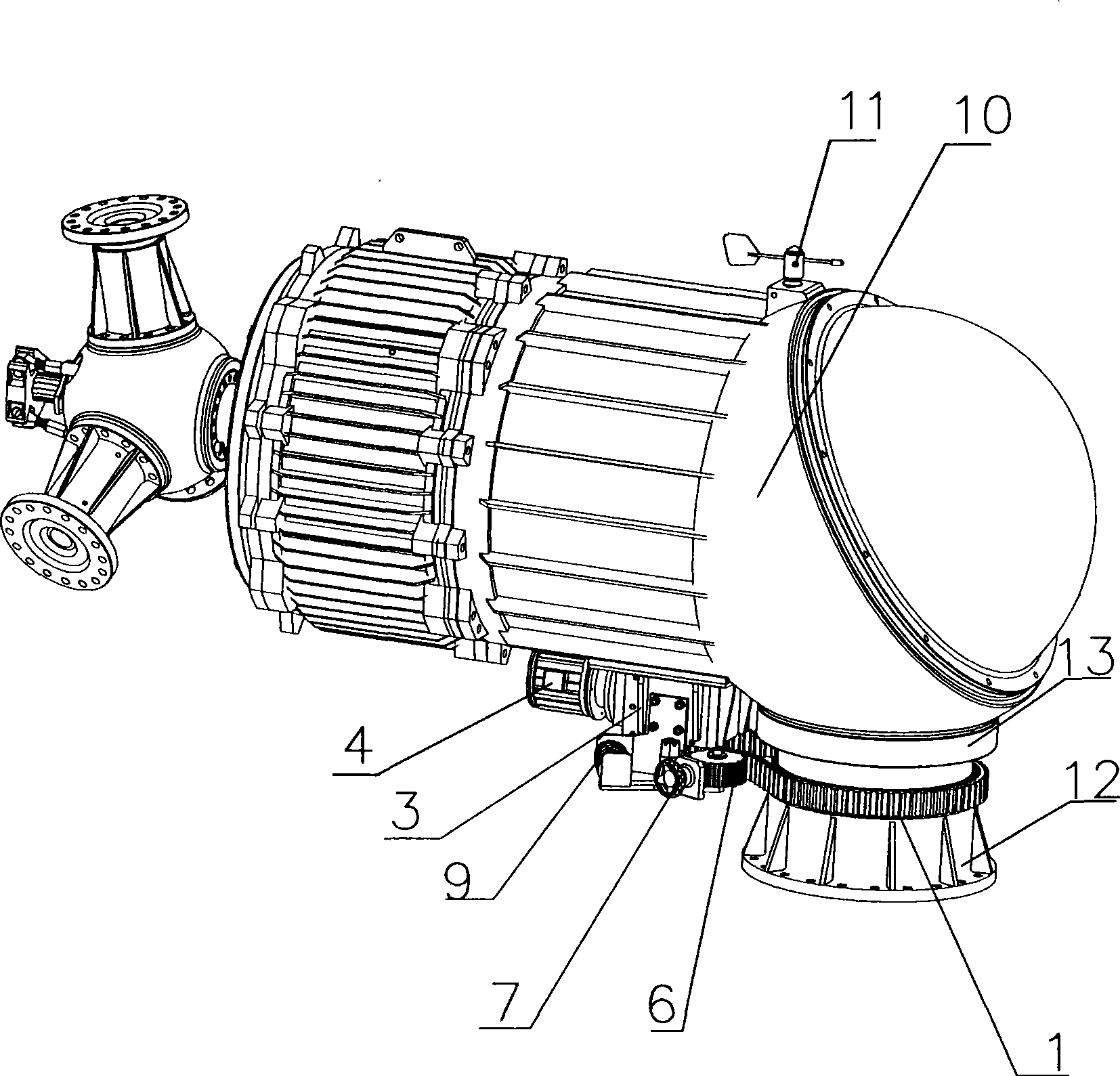
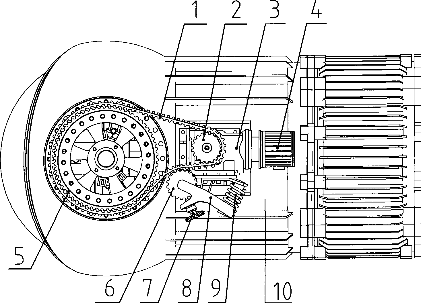
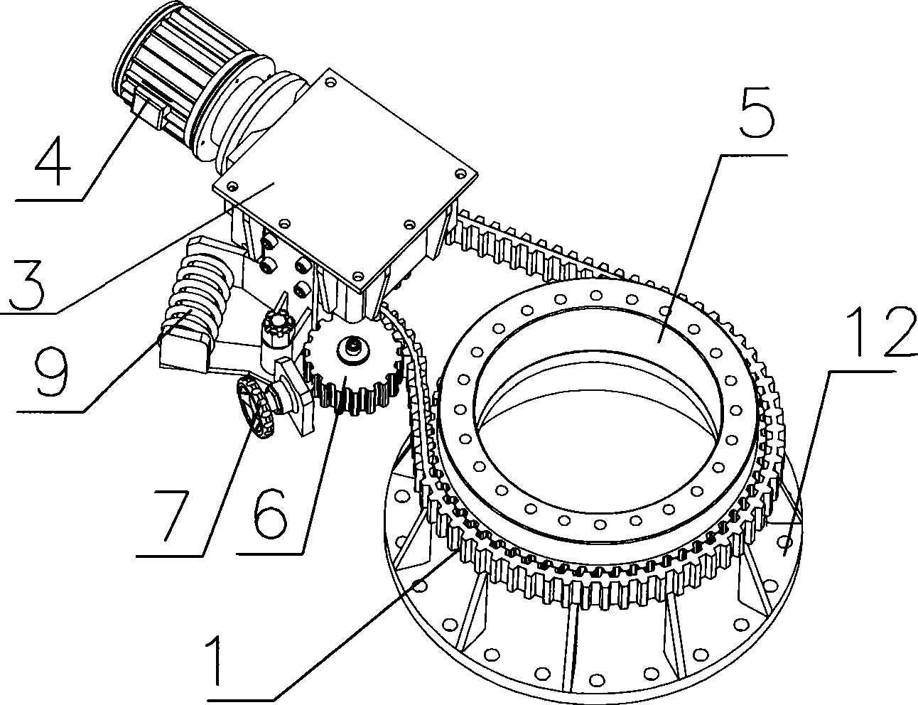
[0012] Such as figure 1 and figure 2 As shown, the rotation damping and stopping mechanism of the downwind wind turbine described in this embodiment includes an anemometer 11, a gear box 3, a motor 4, a small pulley 2, a large pulley 5, a timing belt 1 and a base flange 12. The wind direction indicator 11 is set on the top of the generator 10, the braking torque of the motor 4 increases the torque through the gearbox 3, the motor 4 is connected with the small pulley 2 through the gearbox 3, and the small pulley 2 and the large pulley 5 are synchronized through The belt 1 is connected, the tensioning wheel 6 is installed on the gearbox 3 through the bracket 8, the tensioning wheel 6 is provided with a spring 9 to increase the tensioning force, the large belt wheel 5 and the base flange 12 are fixed by bolts, and the base flange 12 is connected with generator 10 through slewing bearing 13. In the actual running process, the small pulley 2 revolves and rotates around the large...


PUM


Abstract

The invention discloses a downwind aerogenerator gyrodamping and locking mechanism which mainly comprises an anemoscope, a gear case, a motor, a small belt wheel, a big belt wheel, a synchronous belt and a pedestal flange, wherein the motor is connected with the small belt wheel by the gear case, the small belt wheel is connected with the big belt wheel by the synchronous belt, the big belt wheel is connected and fixed with the pedestal by bolts, a tension wheel is arranged on the supporting frame of the gear case, and the supporting frame is provided with a spring matched with the tension wheel. Rotational resistance is relatively large under the condition of no power supply, and speed change between the transmission of the gear case and the synchronous belt increases torque moment so as to achieve good damping effect. The invention has simple operation, and solves the problems of frequent swinging of a generator and unstable power output caused by the influence of wind change, tower shadow effect and other factors in the power generation process of the downwind aerogenerator. The invention increases the work efficiency of the aerogenerator, reduces the wear degree of parts, and is more safe and convenient during maintenance.

Description

technical field [0001] The patent of the present invention relates to the technical field of wind power generator and mechanical transmission. Background technique [0002] In the existing downwind wind turbines, since the wind rotor is located on the downwind side of the main engine and the tower pole, the main engine of the wind turbine tends to sway easily during operation due to the influence of factors such as wind changes and the tower shadow effect, resulting in unstable power output of the generator. Stability, low efficiency, and parts such as slewing bearings are easy to wear due to frequent work. Contents of the invention [0003] The purpose of the patent of the present invention is to provide a rotation damping and stop mechanism for the leeward wind turbine to improve the working efficiency of the downwind wind turbine and reduce the wear and tear of parts in order to solve the above-mentioned deficiencies in the technology. [0004] In order to achieve the ...

Claims


Application Information

Patent Timeline
Patent Type & Authority Applications(China)
IPC IPC(8): F03D1/00F03D11/00F16H7/02F16H7/08F03D9/25F03D15/10
CPCY02E10/72Y02E10/722
Inventor 郭峰赵福盛杨晶明
Owner ZHEJIANG HUAYING WIND POWER GENERATOR
Why Eureka
Try Eureka