
Automatic strain measurement and monitoring system and method thereof

A technology of strain measurement and monitoring system, which is applied in the field of strain monitoring system and its management, can solve problems such as difficulty in installing and using the strain monitoring system, affecting the application of strain monitoring technology, and difficulty in realizing field monitoring objects, so as to improve data collection efficiency and Accuracy, easy installation and use, and reduced volume

Inactive Publication Date: 2011-08-31
CHONGQING JIAOTONG UNIVERSITY
View PDF1 Cites 0 Cited by
  • Summary
  • Abstract
  • Description
  • Claims
  • Application Information

AI Technical Summary

Problems solved by technology

[0004] In some automatic strain monitoring systems, the strain data acquisition device is in working condition for a long time, which consumes a lot of power and has a high failure rate, and the strain monitoring objects are usually located in the field where there is no mains power installed, which is extremely inconvenient for power supply and maintenance, which seriously affects the strain monitoring system. The application of monitoring technology; its strain data acquisition device and management device are usually connected by wires, which brings difficulties to the installation and use of the strain monitoring system
[0005] Such as publication number CN1901418A Chinese Invention Patent Application Publication Specification, which discloses a soil slope distributed optical fiber strain monitoring method and system, wherein the distributed optical fiber is connected to a remote computer through a local computer and the Internet, and its monitoring site The local computer needs the mains power supply to work, and the connection between the local computer and the remote computer through the Internet is also difficult for field monitoring objects.

Method used


Image

  • Automatic strain measurement and monitoring system and method thereof
  • Automatic strain measurement and monitoring system and method thereof
  • Automatic strain measurement and monitoring system and method thereof

Examples


Embodiment Construction

[0047] Preferred embodiments of the present invention will be described in detail below.

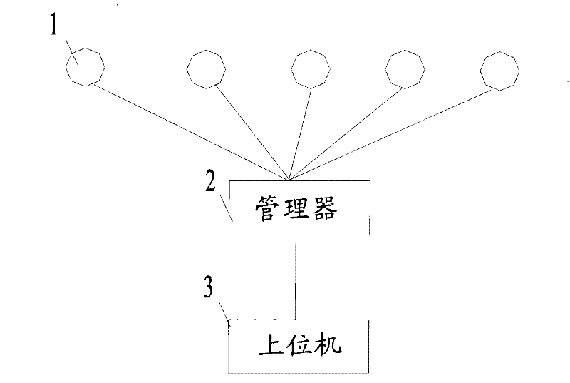
[0048] see figure 1 , the automatic strain measurement and monitoring system of the present embodiment includes a collector 1, a manager 2 and a host computer 3, wherein the collector 1 is used to collect the strain data of the monitored object and transmit it to the manager 2; the manager 2 is used for Receive the strain data transmitted by the collector 1 and transmit it to the host computer 3 to control and manage the collector 1; the host computer 3 is used to send control signals to the manager 2 and receive the strain data transmitted by the manager 2.

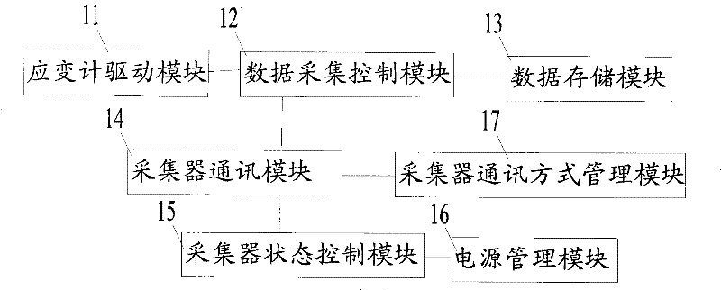
[0049] see figure 2 , the collector 1 includes a strain gauge driver module 11, a data acquisition control module 12, a data storage module 13, a collector communication module 14, a collector state control module 15, a power management module 16 and a communication mode management module 17, and the strain gauge driver module 1...


PUM


Abstract

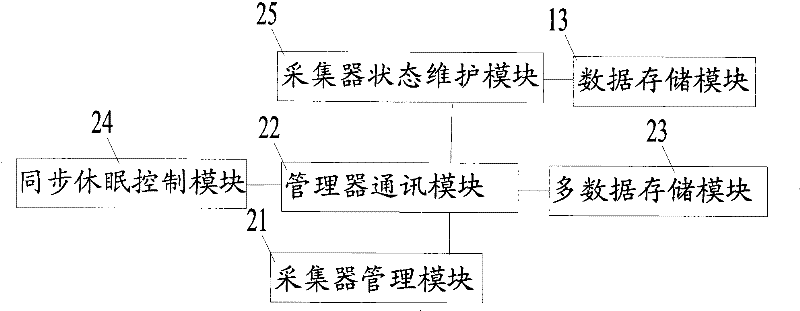
The invention provides an automatic strain measurement and monitoring system and a method thereof. The strain monitoring system comprises a strain gauge, a collector, a manager and a host computer; the collector is used for collecting and transferring strain data from the strain gauge to the manager; the manager is used for receiving and transferring the strain data transferred by the collector to the host computer; the manager comprises a collector management module; the manager is used for receiving control signals from the host computer to control and manage the collector; the host computer emits the control signals to the manager, and receives the strain data transferred by the manager; the communication between the manager and the host computer is realized in a wireless manner, so that a manager can conveniently manage the monitoring system from a long distance without personally collecting the strain data; the invention can measure, even all strain points of a plurality of bridges, a plurality of points simultaneously without assigning people to guard the scene, so that manpower resources can be saved; and furthermore, according to the technical scheme, mutual data storage by the collector realizes interactive data back-up, thereby ensuring the safety of data.

Description

technical field [0001] The invention relates to the technical field of strain measurement and monitoring, in particular to a strain monitoring system and a management method thereof. Background technique [0002] Strain measurement technology is widely used in the state measurement of bridges, dams and other structures. [0003] Most of the existing strain measurement systems are manual detection, such as the strain monitoring of bridges. The current method is to install vibrating wire strain sensors in the bridge structure. When the temperature is stable, the monitoring personnel climb up the bridge with the reading instrument to collect the strain every day. Data, for bridges with multiple sections, it is also necessary to climb up and down all sections through scaffolding in a short period of time, the work intensity is high and the risk is high, and at the same time it is difficult to measure the temperature of multiple sections within the same temperature stabilization ...

Claims


Application Information

Patent Timeline
Patent Type & Authority Patents(China)
IPC IPC(8): G01B21/32
Inventor 张奔牛闫果曹建秋周志祥
Owner CHONGQING JIAOTONG UNIVERSITY
Learn More