Shaped-beam transmission method and shaped-beam transmission device

A beamforming and uniform technology, applied in the field of mobile communications, can solve the problems of reduced resource locations, high resource overhead, and inability to provide beamforming transmission, etc., to reduce resource overhead and achieve simple effects

Active Publication Date: 2009-06-03
DATANG MOBILE COMM EQUIP CO LTD
View PDF0 Cites 32 Cited by
  • Summary
  • Abstract
  • Description
  • Claims
  • Application Information

AI Technical Summary

Problems solved by technology

[0006] The existing LTE system supports beamforming transmission, but the UsRS mapping method required for beamforming does not propose a specific solution
When using the above subframe structure for beamforming transmission, CsRS and UsRS exist at the same time. At this time, due to figure 1 Ri is the mapping position of CsRS, and UsRS can only be placed at the location of the data symbol ( figure 1 In the position occupied by D in D), correspondingly, the resource positions that can be used to transmit data symbols will be reduced. Obviously, this will lead to a relatively large resource overhead for reference signal transmission in the subframe
[0007] On the other hand, when performing beamforming transmissi...

Method used


Image

  • Shaped-beam transmission method and shaped-beam transmission device
  • Shaped-beam transmission method and shaped-beam transmission device
  • Shaped-beam transmission method and shaped-beam transmission device

Examples


Embodiment Construction

[0043]In order to make the object, technical solution and advantages of the present invention clearer, the present invention will be further described in detail below with reference to the accompanying drawings and examples.

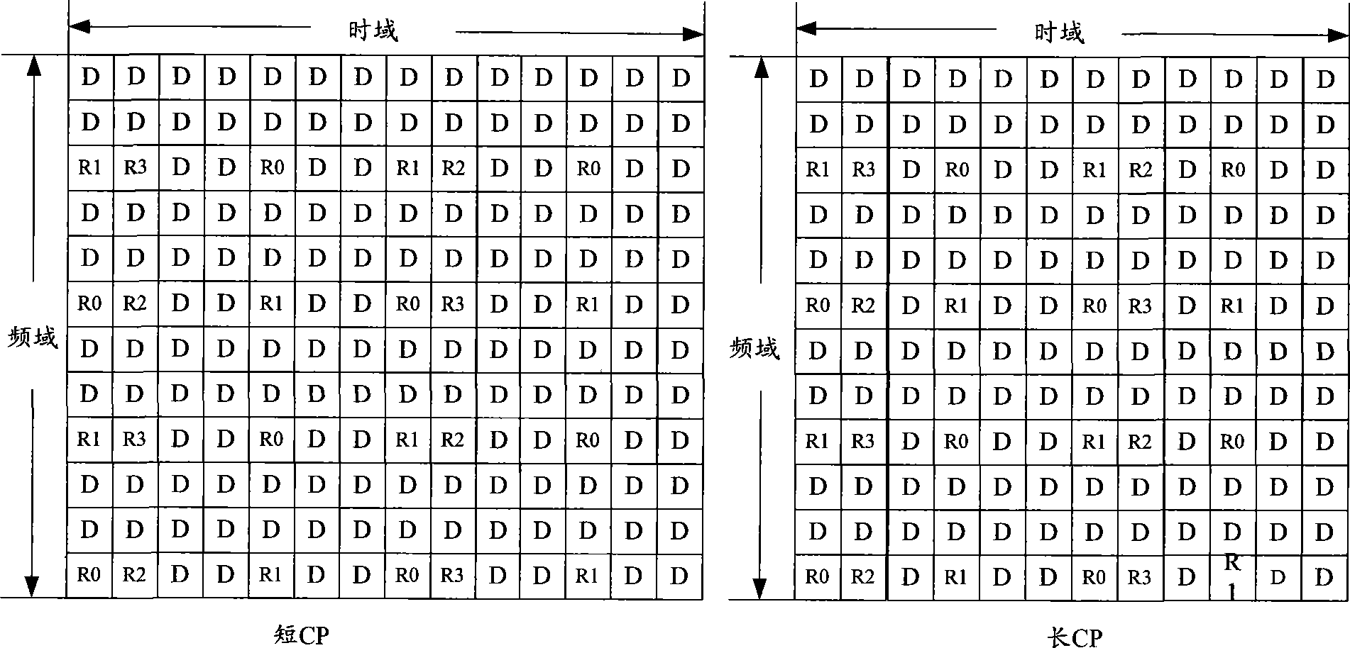
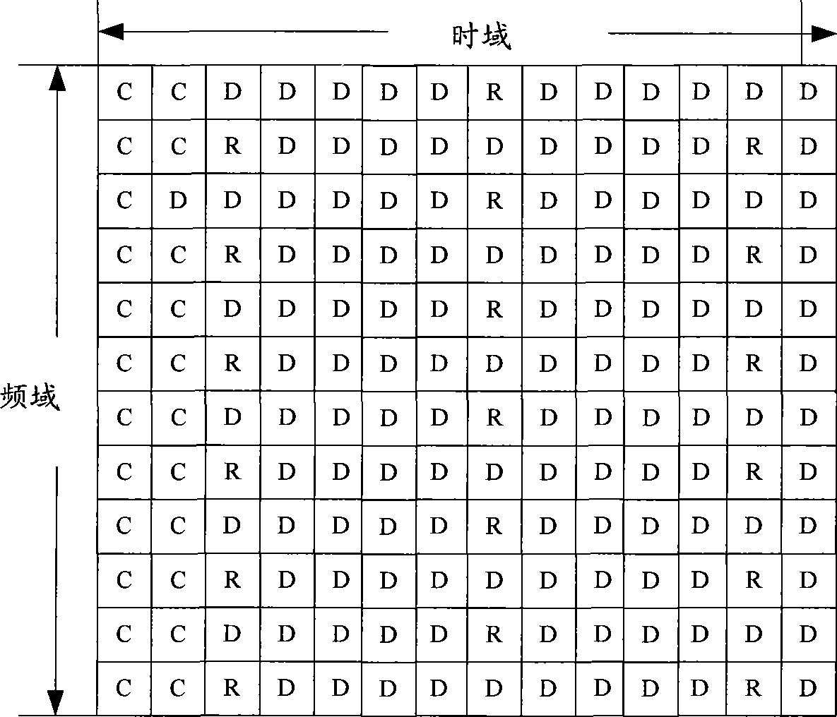
[0044] When performing beamforming, the terminal needs to use the UsRS for channel estimation, and at this time, the subframe includes two kinds of reference signals: CsRS and UsRS. Since the UsRS is used, the CsRS can be appropriately reduced or even not used to reduce system resource overhead. In this case, the system defines a new subframe structure for beamforming transmission.

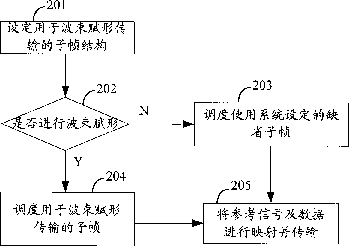
[0045] An embodiment of the present invention provides a method for beamforming transmission, the process of the method is as follows figure 2 shown, including:

[0046] Step 201, the system defines a new subframe structure for beamforming transmission, and the default setting in the system is to use the subframe structure in the prior art for non-beamforming transmission...


PUM


Abstract

The invention discloses a shaped-beam transmission method which comprises the following steps: a system sets a subframe structure for performing shaped-beam transmission, wherein, the step further comprises the sub-steps of setting previous n OFDM symbols in the subframe for purpose of transmitting a control signaling and setting the number of OFDM symbols, which are not the previous n OFDM symbols and are used by user exclusive reference signals, and frequency domain spaces of the reference signals on the same data layer, wherein, n is not less than 1 and mapping positions of the reference signals on difference data layers are not overlapped with each other; and when the system judges to perform the shaped-beam transmission, the subframe structure is dispatched to map and transmit the reference signals. The invention also discloses a shaped-beam transmission device which comprises a subframe structure setting module, a shaped-beam judging module and a mapping and transmission executing module. In the invention, the subframe structure is newly set so that the transmission of the user exclusive reference signals can be supported and the shaped-beam transmission can be performed; and meanwhile, resource consumption of the system is reduced and the method and the device are easy to be realized.

Description

technical field [0001] The present invention relates to mobile communication technology, in particular to a method and device for beamforming transmission. Background technique [0002] Currently, the Third Generation Mobile Communication System Standardization Organization (3GPP) has initiated a research project on the Long Term Evolution (LTE) of the 3G radio interface technology. According to the research progress, the current LTE standard version defines a cell-specific reference signal (Cell-specified Reference Signal, CsRS) mapping scheme. [0003] All Orthogonal Frequency Division Multiplexing (OFDM) symbols in the subframe structure are used for unicast transmission and do not support broadcast transmission. At this time, in addition to data symbols and control signaling, there can be two types of The reference signal includes CsRS and user-specific reference signal (UE-specified Reference Signal, UsRS), wherein the CsRS occupies 4 antenna ports for transmission, an...

Claims


Application Information

Patent Timeline
IPC IPC(8): H04B7/06H04B7/08
Inventor 索士强林亚男缪德山
Owner DATANG MOBILE COMM EQUIP CO LTD
Why Eureka
Try Eureka