
Band-pass box in the supporting structure of a vehicle

A technology for supporting structures and vehicles, applied in vehicle components, transportation and packaging, etc., can solve the problems of occupying door frame space and reducing bearing space, etc.

Inactive Publication Date: 2011-03-09
DAIMLER AG
View PDF2 Cites 0 Cited by
  • Summary
  • Abstract
  • Description
  • Claims
  • Application Information

AI Technical Summary

Problems solved by technology

For this purpose, it is known to embed special cavity spaces (so-called loudspeaker boxes) at appropriate points in the vehicle, but this mostly leads to a reduction in the load space provided for the vehicle or takes up space in the door frame

Method used


Image

  • Band-pass box in the supporting structure of a vehicle
  • Band-pass box in the supporting structure of a vehicle
  • Band-pass box in the supporting structure of a vehicle

Examples


Embodiment Construction

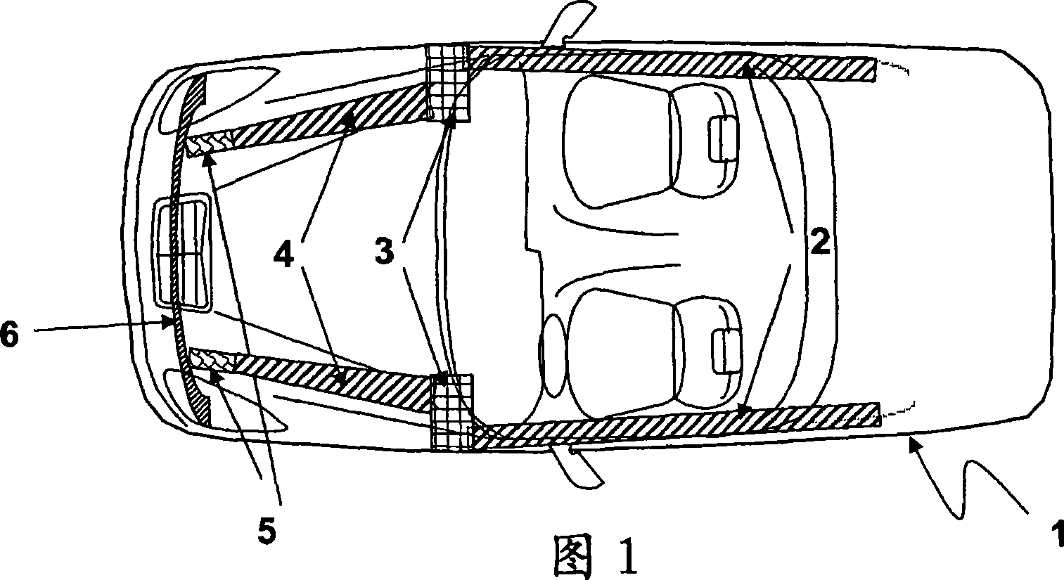
[0023] figure 1 A vehicle 1 is shown by way of example with the usual support structure elements 2 , 3 , 4 , 5 , 6 ; In order to obtain the desired space for the loudspeaker enclosures, it is conceivable within the scope of the invention to couple individual or all support structure elements 2 , 3 , 4 , 5 , 6 acoustically to one another.

[0024] exist figure 2 A loudspeaker enclosure according to the invention is shown by way of example in . In this case, the overall space of the loudspeaker enclosure is formed by the sill space 2 , the transverse beam 3 and the longitudinal beam 4 . A sound transducer 10 is inserted between the transverse beam 3 and the longitudinal beam 4 . In the example shown here, the acoustic transducer 10 is adapted in its dimensions to the dimensions of the supporting structure, in particular by means of a suitably designed loudspeaker basket, in such a way that it divides the entire space into two mutually separated sub cavity. Here, the closed...


PUM


Abstract

A sound system which has, for example, a radio, a cassette and a CD player is usually already installed in cars as standard or as an option. In addition, a better sound system comprises a box system which has a tweeter and a woofer. In order to provide a speaker box which is suitable particularly for dispensing frequencies below 150 Hz and at the same time has neat pulses accompanied at the same time by little distortion, pulse dynamics and is highly effective, a sound transducer (10) is introduced into the supporting structure of the vehicle. This takes place in such a manner that subcompartments which are separated from each other adjoin each of its two membrane sides. In this case, the two subcompartments of the speaker box are formed by at least two elements (2, 3, 4) of the supporting structure of the vehicle (1). The sound transducer (10) is particularly integrated into a region in which two elements (2, 3, 4) of the supporting structure meet each other, thus resulting in an installation position which can be realized in a structurally and economically favourable manner.

Description

technical field [0001] The invention relates to a loudspeaker enclosure for a vehicle in a support structure for a motor vehicle, the loudspeaker enclosure comprising at least one active acoustic transducer housed within the loudspeaker enclosure, the acoustic transducer being positioned such that the two sides of the membrane are respectively in close proximity to each other A divided sub-cavity, wherein at least a portion of the sound waves generated in the sub-cavity by the acoustic transducer are conducted to the interior of the vehicle through at least one inner channel. Background technique [0002] Audio equipment, such as radios, tape players and CD players, is usually installed as standard or as an option in motor vehicles. Further preferred audio equipment includes a speaker system with a tweeter and a bass speaker. [0003] Since the speakers radiate sound into the vehicle interior, connecting the speakers to a resonant space not in communication with the interio...

Claims


Application Information

Patent Timeline
Patent Type & Authority Patents(China)
IPC IPC(8): B60R11/02
CPCB60R13/0237
Inventor K·林哈德N·涅姆奇克
Owner DAIMLER AG
Learn More