Microplate

A technology of microplates and boundary parts, which is applied to the analysis of materials, instruments, etc., can solve problems such as troublesome troubles and rising analysis costs, and achieve the effect of suppressing costs

Active Publication Date: 2012-07-04
BECKMAN COULTER INC
View PDF1 Cites 0 Cited by
  • Summary
  • Abstract
  • Description
  • Claims
  • Application Information

AI Technical Summary

Problems solved by technology

For this reason, it is necessary to focus again on the identification information and take an image, and there is a problem that it is troublesome to obtain the data necessary for the analysis.
[0006] In addition, in order to change the focus position, it is necessary to us

Method used


Image

  • Microplate
  • Microplate
  • Microplate

Examples


Embodiment Construction

[0031] Hereinafter, the best mode for carrying out the present invention (hereinafter referred to as "embodiment") will be described with reference to the drawings.

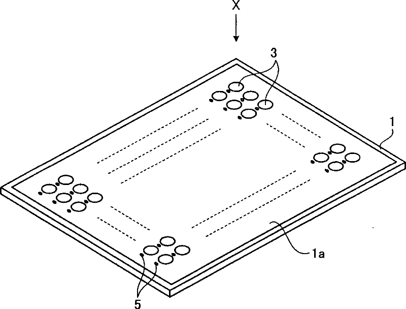
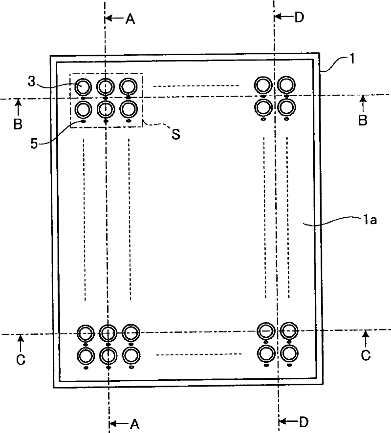
[0032] figure 1 It is a perspective view showing a schematic configuration of a microplate according to an embodiment of the present invention. and, figure 2 yes figure 1 Front view of the microplate seen from the arrow X direction. The microplate 1 shown in these figures has a circular opening, and a plurality of small wells 3 of slightly concave reaction containers for dispensing a subject or a reagent and generating a reaction are arranged in a matrix. . On the surface 1a (first surface) on the front side passing through the openings of the plurality of small wells 3 and the surface 1b (second surface) on the back side pointing to the opposite side, and at predetermined positions near the corresponding small wells 3 The well identification information display part 5 which shows the well identification ...


PUM


Abstract

The present invention provides a microplate in which not much procedures are required for obtaining accurate data for analyzing a specimen, and the cost required for analysis can be suppressed. The microplate comprises a surface (first surface) passing the opening plane of a well, a surface (second surface) directing the opposing side, and a section provided on a surface included in the boundary portion of adjoining wells and indicating information for identifying each of a plurality of wells. The thickness at the boundary portion of adjoining wells is substantially identical to the depth of the well.

Description

technical field [0001] The present invention relates to a microplate configured by arranging a plurality of wells as reaction containers for analyzing components of a subject in a matrix. Background technique [0002] When analyzing components of a subject such as blood or body fluid, a microplate configured by arranging a plurality of reaction vessels called wells in a matrix is ​​often used (for example, refer to Patent Document 1). A sample containing a substance to be analyzed and a reaction reagent containing a substance that promotes a reaction between the substance to be analyzed and the antigen-antibody are dispensed into each well of the microplate. Then, after a predetermined time has elapsed from the start of the dispensing, the reaction generated in the small well is imaged by an imaging device such as a CCD (Charge Coupled Device) camera, and the components of the subject are analyzed using the image data obtained by the imaging. analysis. [0003] Conventiona...

Claims


Application Information

Patent Timeline
IPC IPC(8): G01N35/02
CPCG01N35/028
Inventor 竹内知彦
Owner BECKMAN COULTER INC
Why Eureka
Try Eureka