Radio communication device and radio communication method

A wireless communication device and signal transmission technology, applied in multiplex communication, modulated carrier system, transmission system, etc., can solve the problem of low correlation of antenna received signals

Inactive Publication Date: 2009-06-03
PANASONIC CORP
View PDF2 Cites 25 Cited by
  • Summary
  • Abstract
  • Description
  • Claims
  • Application Information

AI Technical Summary

Problems solved by technology

[0005] On the other hand, for example, information on spatial multiplexing technology is disclosed in Non-Patent Document 2; spatial multiplexing transmission can be realized in a propagation environment in which a transmitter and a receiver each have a plurality of antenna elements , and the received signal correlation between the antennas is very low

Method used


Image

  • Radio communication device and radio communication method
  • Radio communication device and radio communication method
  • Radio communication device and radio communication method

Examples


no. 1 example

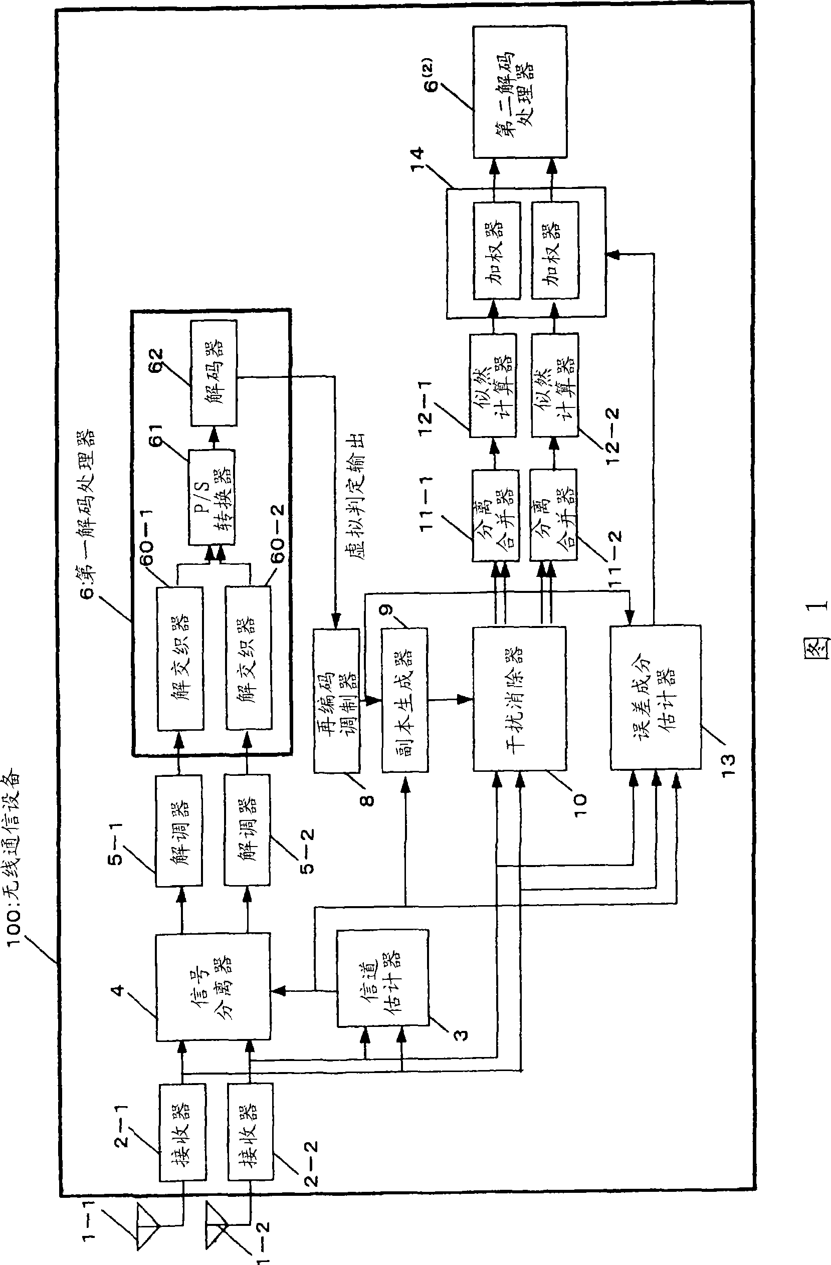
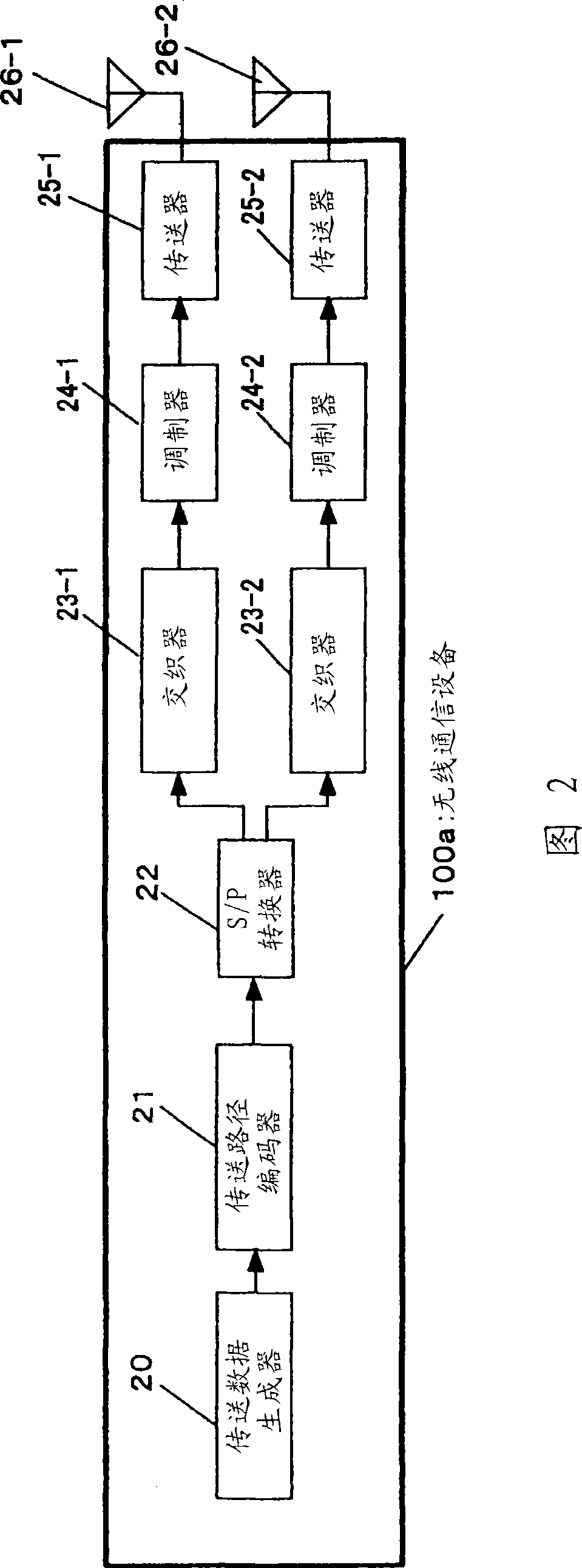
[0116] FIG. 1 is a diagram showing the configuration of a wireless communication device 100 in the first embodiment of the present invention. Only the reception configuration is shown in the wireless communication device 100 of FIG. 1 , whereas the transmission configuration is shown in the wireless communication device 100 a of FIG. 2 . The reception configuration in the embodiment is a configuration in which iterative decoding is performed using a Parallel Interference Canceller (PIC). The operation will be discussed below in the order of Figures 1 and 2:

[0117] First, the transmission operation of the wireless communication device 100a will be discussed with reference to FIG. 2 . The wireless communication device 100a performs spatial multiplexing transmission of M transmission sequences from a plurality (M, M>1) of antennas 26-1 to 26-M (hereinafter will be referred to as spatial multiplexing streams) . FIG. 2 shows the configuration of the wireless communication devi...

no. 2 example 1

[0203]FIG. 9 is a diagram showing the configuration of a wireless communication device 200 in the second embodiment of the present invention. Only the reception configuration is shown in the wireless communication device 200 of FIG. 9 , whereas the transmission configuration is shown in the wireless communication device 201 of FIG. 10 . In the first embodiment, a transmission and reception configuration for performing space multiplexing transmission is shown, and a second embodiment shows a case where M=1 in the first embodiment, no space is performed Transmit and receive configurations for multiplexed transports. This operation will be discussed in order using FIGS. 9 and 10 below.

[0204] First, the transmission operation of the wireless communication device 201 will be discussed with reference to FIG. 10 . The wireless communication device 201 transmits a transmission sequence (hereinafter will be referred to as a transmission stream) from an antenna 26 . In FIG. 10, th...

no. 3 example

[0257] FIG. 4 is a diagram showing the configuration of a wireless communication device 100b in the third embodiment of the present invention. In the wireless communication device 100b of FIG. 4, only the reception configuration is shown, and the transmission configuration is the same as that of the wireless communication device 100a shown in FIG. 2, and thus the transmission operation will not be discussed again.

[0258] As a reception configuration in this embodiment, it shows a configuration in which iterative decoding is performed using a parallel interference canceller (PIC). The third embodiment differs from the first embodiment in that a wireless communication device has an error component estimator 15 for estimating an error component based on an input signal, which is different from the error component estimator 13 in the first embodiment. That is, error component estimator 15 estimates error components based on the outputs of stream reception quality estimator 7 and...


PUM


Abstract

When cancelling interference in a radio communication device for repeatedly decoding/receiving a spatially multiplexed signal, if a symbol of erroneous judgment is contained or if an error factor caused by a propagation channel estimation error or hardware error (carrier frequency error, sampling frequency error) is contained, reception characteristic is degraded by an interference signal component. The radio communication device (100) includes an error estimation unit (13) for estimating an error of a replica signal during interference cancelling and a weighting unit (14) for weighting likelihood information for a spatially multiplexed signal which is demultiplexed and multiplexed after the interference cancelling. Accordingly, even if an error of the replica signal during interference cancelling is contained, it is possible to obtain preferable reception characteristic.

Description

technical field [0001] The present invention relates to wireless communication devices for iteratively decoding and receiving signals. technical background [0002] In recent years, the demand for high-performance and high-speed wireless communication has grown rapidly, and research on methods to further effectively improve the use efficiency of limited frequency resources is very active. As one of these approaches, the focus is on the use of airspace. One of the techniques to use the airspace is to use an adaptive array antenna (Adaptive Antenna). In an adaptive array antenna, a received signal may be multiplied using a weighting coefficient to adjust amplitude and phase (hereinafter, the weighting coefficient will be referred to as "weight"). As they are adjusted, the adaptive array antenna can stably receive signals from any desired direction and suppress interference wave directions, thus making it possible to increase the communication capacity of the system. [0003...

Claims


Application Information

Patent Timeline
Patent Type & Authority Applications(China)
IPC IPC(8): H04L1/00H04B17/00H04J99/00
CPCH04L1/005H04L27/2647H04L25/03324H04L25/0328H04B17/0075H04L25/03318H04B17/373
Inventor 岸上高明向井裕人冈村周太
Owner PANASONIC CORP
Why Eureka
Try Eureka