Two-way sealing butterfly valve

A two-way sealing, butterfly valve technology, applied in the direction of lift valve, valve device, engine components, etc., can solve the problem of unsatisfactory sealing effect and reverse sealing effect, and achieve the effect of low cost, simple product structure and reliable two-way sealing.

Inactive Publication Date: 2009-06-10
JIANGSU SHENTONG VALVE
View PDF0 Cites 9 Cited by
  • Summary
  • Abstract
  • Description
  • Claims
  • Application Information

AI Technical Summary

Problems solved by technology

[0003] In order to overcome the shortcomings of the existing two-way sealing butterfly valve sealing effect, especially the unsatisfactory reverse sealing effect, the present invention provides a two-way sealing butterfly valve

Method used


Image

  • Two-way sealing butterfly valve

Examples


Embodiment Construction

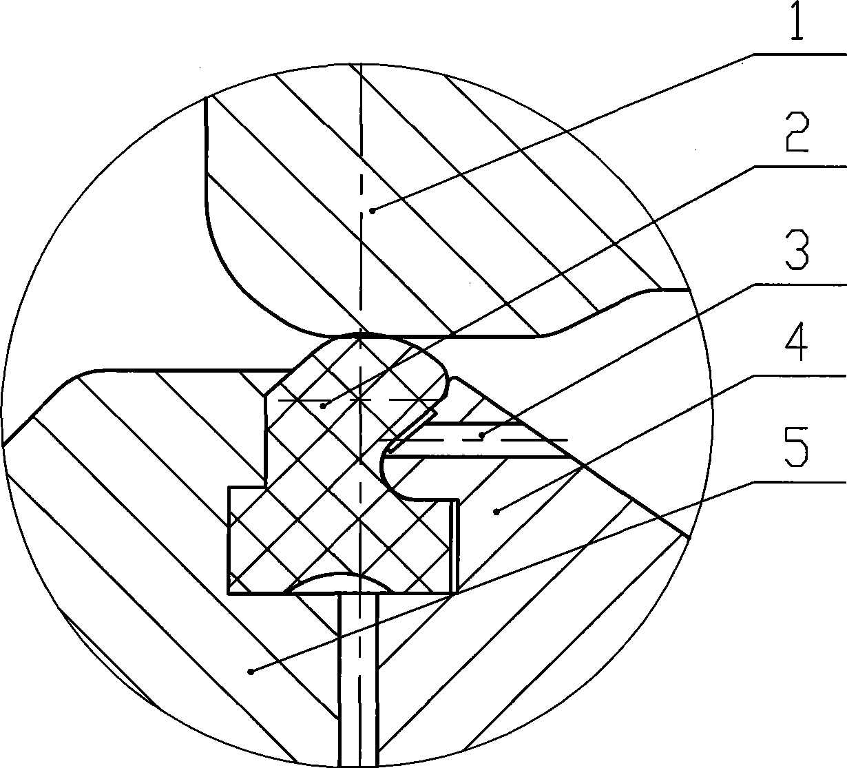
[0009] Such as figure 1 As shown, a two-way sealing butterfly valve includes a valve seat 1, a rubber sealing ring 2, a butterfly plate 5, and a pressure plate 4. The rubber sealing ring 2 is fixed on the butterfly plate 5 with bolts through the pressure plate 4, and the sealing surface of the valve seat 1 is a On the plane, there is a groove at the contact place between the rubber sealing ring 2 and the pressing plate 4, and the ventilation holes 3 are evenly distributed along the circumference of the pressing plate 4 corresponding to the groove of the rubber sealing ring 2. When the valve is reversely pressed, the rubber sealing ring 2 tends to turn up and press against the sealing surface of the valve seat 1. The greater the reverse pressure, the better the sealing effect.


PUM


Abstract

The invention provides a bidirectional sealing butterfly valve, comprising a valve seat, a rubber sealing ring, a butterfly board and a pressure board. The rubber sealing ring is fixed on the butterfly board through the pressure board by the bolts, the sealing surface of the valve seat is a plane, the contact place of the rubber sealing ring and the pressure board has a groove, and air holes are uniformly distributed along a circle on the pressure board corresponding to groove of the rubber sealing ring. The butterfly valve has the advantages of simple product structure, low cost and realizing bidirectional sealing reliably.

Description

technical field [0001] The invention relates to a valve, in particular to a bidirectional sealing butterfly valve. Background technique [0002] In the prior art, there are many types of butterfly valves capable of bidirectional sealing, with different performances, and various structures of the sealing pair, but generally speaking, the sealing effect, especially the reverse sealing effect, is not ideal. Contents of the invention [0003] In order to overcome the disadvantages of the existing two-way sealing butterfly valve with unsatisfactory sealing effect, especially the unsatisfactory reverse sealing effect, the invention provides a two-way sealing butterfly valve. [0004] The technical solution adopted by the present invention to solve the technical problem is a two-way sealing butterfly valve, including a valve seat, a rubber sealing ring, a butterfly plate, and a pressure plate. The rubber sealing ring is fixed on the butterfly plate with bolts through the pressure...

Claims


Application Information

Patent Timeline
Patent Type & Authority Applications(China)
IPC IPC(8): F16K1/22F16K1/226
Inventor 沈捷美于强陈华妹
Owner JIANGSU SHENTONG VALVE
Why Eureka
Try Eureka