Method for little air-gap generator motor assembling

A generator rotor and small air gap technology, which is applied in the manufacture of motor generators, electrical components, electromechanical devices, etc., can solve the problems of not being able to adopt the wearing method, wearing the rotor, and not being able to use arc-shaped skateboards, etc., to achieve strong practicability , Reduce labor intensity and improve work efficiency

Active Publication Date: 2009-06-10
SHANGHAI ELECTRIC POWER GENERATION EQUIPMENT CO LTD
View PDF0 Cites 4 Cited by
  • Summary
  • Abstract
  • Description
  • Claims
  • Application Information

AI Technical Summary

Problems solved by technology

[0003] There is a thin sleeve between the rotor and the iron core of the evaporative cooling generator. Unlike the iron core, the thin sleeve cannot bear the weight of the rotor, so the arc-shaped slide plate cannot be used to wear the rotor, and the air gap is reduced to 24mm (traditional wear The installed air gap is 49mm), so the evaporative cooling generator rotor cannot be installed in the traditional way, that is, the arc-shaped slide plate is used to install the generator rotor

Method used


Image

  • Method for little air-gap generator motor assembling
  • Method for little air-gap generator motor assembling
  • Method for little air-gap generator motor assembling

Examples


Embodiment

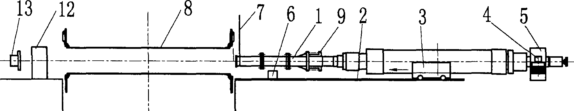
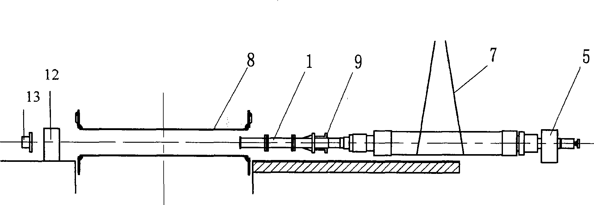
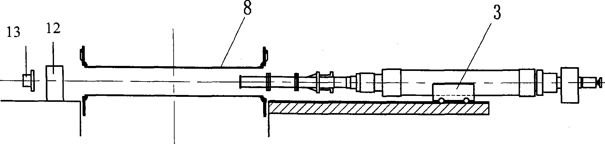
[0022] Such as figure 1 As shown in the figure, it is a schematic diagram of the tooling of the generator rotor. The tooling of the rotor of the generator consists of a connecting shaft 1, a guide rail 2, a trolley 3, a bracket 4, a excitation end bearing seat 5, a spacer 6, and a crane rope 7 , Sleeve 8, generator coupling 9, rotor bearing gear 10, rotor 11, steam end bearing block 12 and steam turbine coupling 13 are formed. The connecting shaft 1 is composed of at least three detachable short connecting shafts, which are connected to the rotor generator coupling 9 by bolts, and its function is to extend the rotor 11 so that when the rotor protrudes from the steam end, it can hang the connecting shaft. Shaft 1; trolley 3 can steadily carry rotor 11 and move forward slowly on guide rail 2; when trolley 3 drags rotor 11 at generator rotor bearing gear 10, bracket 4 should be used to cushion trolley 3, and hoop Firmly tie the rotor 11 on the trolley 3; the excitation end beari...


PUM


Abstract

The invention relates to a method for mounting a generator rotor with small air gap. The method comprises the following specific steps: a guide rail is fixed and is provided with a trolley; the guide rail is provided with a sleeve in the extending direction; a bearing seat at the excitation end is hung on the rotor; a generator coupler is arranged on the rotor; a connecting shaft is arranged on the generator coupler; a lifting rope of a crane lifts the rotor to the upper part of the guide rail; the rotor is placed on the trolley, and the trolley drags the rotor to pass through the sleeve; the connecting shaft extends out from the steam end of the sleeve and hangs the connecting shaft; the bearing seat at the excitation end is removed; the trolley retreats from a bearing shift of the rotor; the rotor is dragged by a bracket; the trolley drags the rotor to move forward; the rear section of the connecting shaft is filled up at the steam end through a pad block, and the front section of the connecting shaft is detached; according to the method, three sections of the connecting shaft are detached by sections; the trolley and the guide rail are detached, and the bearing seat at the excitation end is hung on the rotor; and the rotor is hung to the proper position. The method has the advantages that the method has strong practicability, relieves labor intensity, strengthens safety coefficient, improves working efficiency, provides reliable foundation for solving similar difficult problems and has popularization value.

Description

technical field [0001] The invention relates to a method for threading a generator rotor with a small air gap, which can solve the problems of smoothly threading a generator rotor in a limited state with a small air gap, and belongs to the technical field of threading a generator rotor. Background technique [0002] Generator rotor assembly is usually done by placing an arc-shaped slide plate on the stator core. The rotor rests on the arc-shaped slide plate through the journal bracket. One end pulls the rotor, and the other end lifts the rotor, and slowly inserts the rotor into the generator iron core. Inside. [0003] There is a thin sleeve between the rotor and the iron core of the evaporative cooling generator. Unlike the iron core, the thin sleeve cannot bear the weight of the rotor, so the arc-shaped slide plate cannot be used to wear the rotor, and the air gap is reduced to 24mm (traditional wear The installed air gap is 49mm), so the traditional method of installing ...

Claims


Application Information

Patent Timeline
IPC IPC(8): H02K15/00
Inventor 张燕陈锦辉干保良黄兆款杨立武
Owner SHANGHAI ELECTRIC POWER GENERATION EQUIPMENT CO LTD
Why Eureka
Try Eureka