Coil inserting method and coil inserting device

A coil insertion and coil installation technology, applied in the direction of prefabricated winding embedded in the motor, laying solid insulation, etc., can solve the problems of reduced motor efficiency and long coil circumference, and achieve the effect of reducing damage

Inactive Publication Date: 2009-06-10
MITSUBISHI ELECTRIC CORP
View PDF1 Cites 11 Cited by
  • Summary
  • Abstract
  • Description
  • Claims
  • Application Information

AI Technical Summary

Problems solved by technology

[0005]In this case, the coil circumference length becomes longer than the coil circumference length w

Method used


Image

  • Coil inserting method and coil inserting device
  • Coil inserting method and coil inserting device
  • Coil inserting method and coil inserting device

Examples


Embodiment Construction

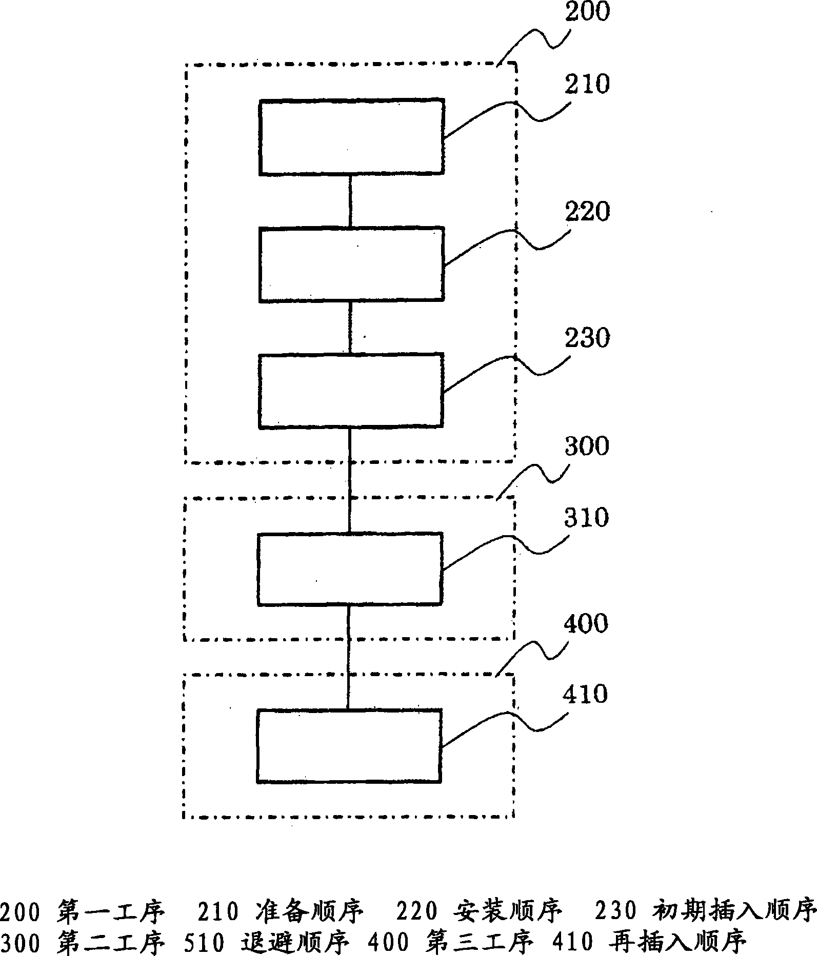
[0034] Implementation form 1

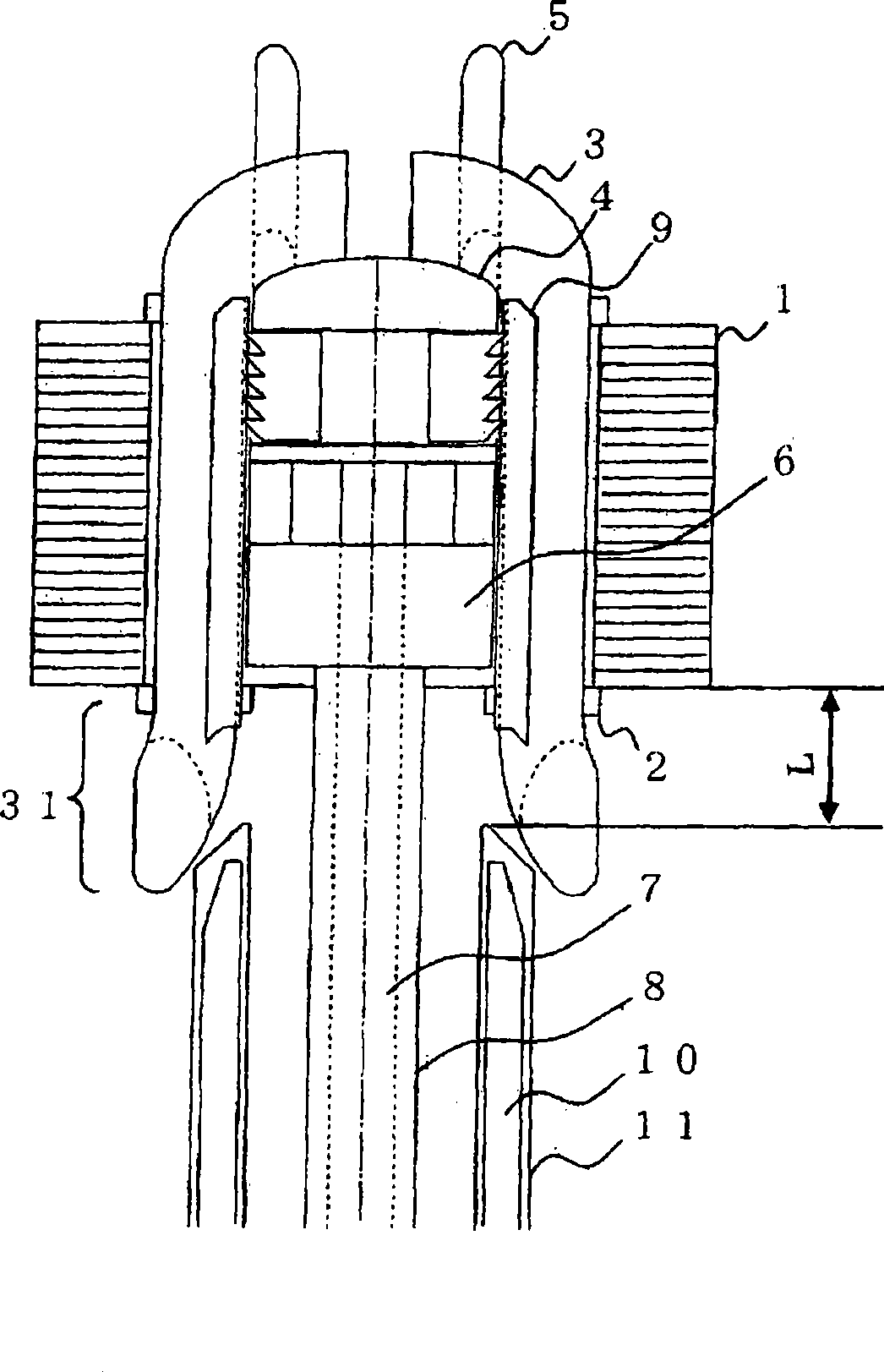
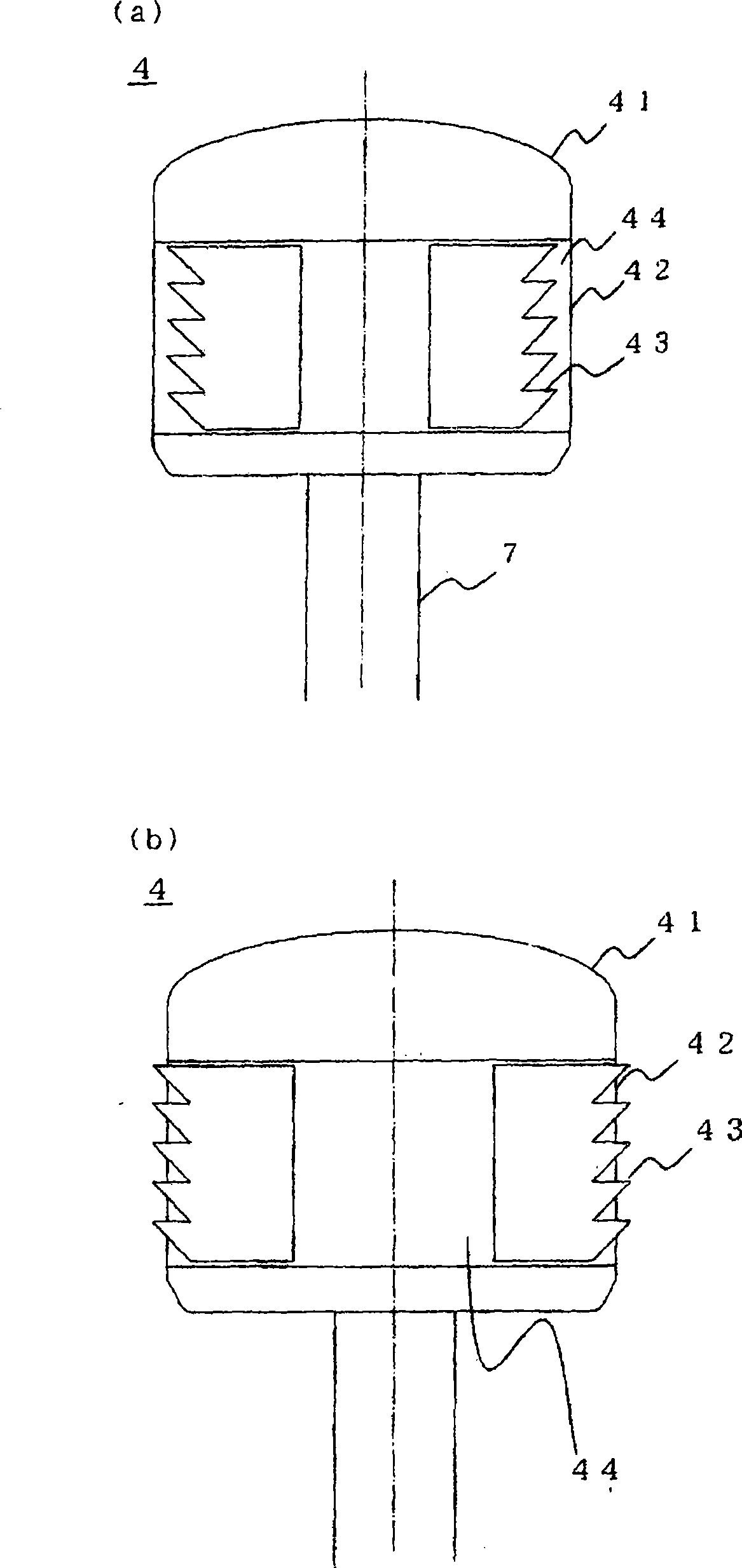
[0035] According to the invention of Embodiment 1, using the coil insertion device equipped with the blade, the separator, the slot wedge pusher, and the slot wedge guide, the wound coil and each slot insertion unit of the coil are bundled and insulated. When the slot wedge is inserted into the slot of the iron core constituting the motor, the coil insertion end of the iron core is separated from the front end of the slot wedge guide by a predetermined distance during the coil insertion process, and then the coil insertion process is continued.

[0036] figure 1 It is a diagram showing a method of inserting a coil into a core slot using the coil inserting device according to Embodiment 1 of the present invention, and shows a state when the coil insertion is completed. Here, the slot refers to a space formed by a stator core for winding a coil and forming a magnetic pole, and a plurality of teeth that are protruding protrusions protruding in the...


PUM


Abstract

The present invention is to reduce interference of a slot wedge guide member and coils configured for guide the slot wedge inserted together when winding coils are inserted into stator core of a motor, and to reduce damage along the coils inserted together even for coils with short perimeter. According to the invention, processes of enlarging distance between the slot wedge guide member to the coils insertion end of the core are added after a part of normal coils insertion processes, then process of inserting coils is continue in condition that the coils insertion end of the core move away from the slot wedge guide member.

Description

technical field [0001] The present invention relates to a coil insertion method and a coil insertion device for preventing interference between a coil and a coil insertion jig (hereinafter referred to as a wedge guide) due to shortening of the circumference of the coil. Background technique [0002] An electric motor consists of a stator and a movable element forming the magnetic poles. Among them, the stator is composed of an iron core composed of a yoke portion and a plurality of teeth (teeth) protruding in the inner diameter direction arranged on the inner periphery of the yoke portion, and a yoke formed between the teeth. A space called a slot is wound around a coil on each tooth, and when electricity is supplied to each coil, each tooth forms a magnetic pole. [0003] As a method of winding the coils on the teeth, a method called a coil insertion device is generally used to insert the pre-wound coils into the slots of the iron core constituting the stator. [0004] In...

Claims


Application Information

Patent Timeline
IPC IPC(8): H02K15/06H02K15/10
Inventor 本桥昌也荒井利夫秋田裕之
Owner MITSUBISHI ELECTRIC CORP
Why Eureka
Try Eureka