Vibration absorption bonding apparatus

A lap joint device, vibration isolation technology, applied in the direction of circuit layout on the support structure, etc.

Inactive Publication Date: 2009-06-10
INVENTEC CORP
View PDF0 Cites 1 Cited by
  • Summary
  • Abstract
  • Description
  • Claims
  • Application Information

AI Technical Summary

Problems solved by technology

[0004] However, for auxiliary structures that can vibrate (such as cooling fans), the increase in the speed of the fan will cause the vibration to become severe. There is a space for vibration isolation between them, so it is necessary to further improve the effect of vibration isolation

Method used


Image

  • Vibration absorption bonding apparatus
  • Vibration absorption bonding apparatus
  • Vibration absorption bonding apparatus

Examples


Embodiment Construction

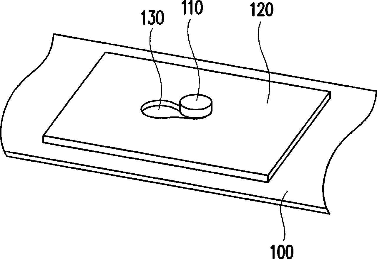
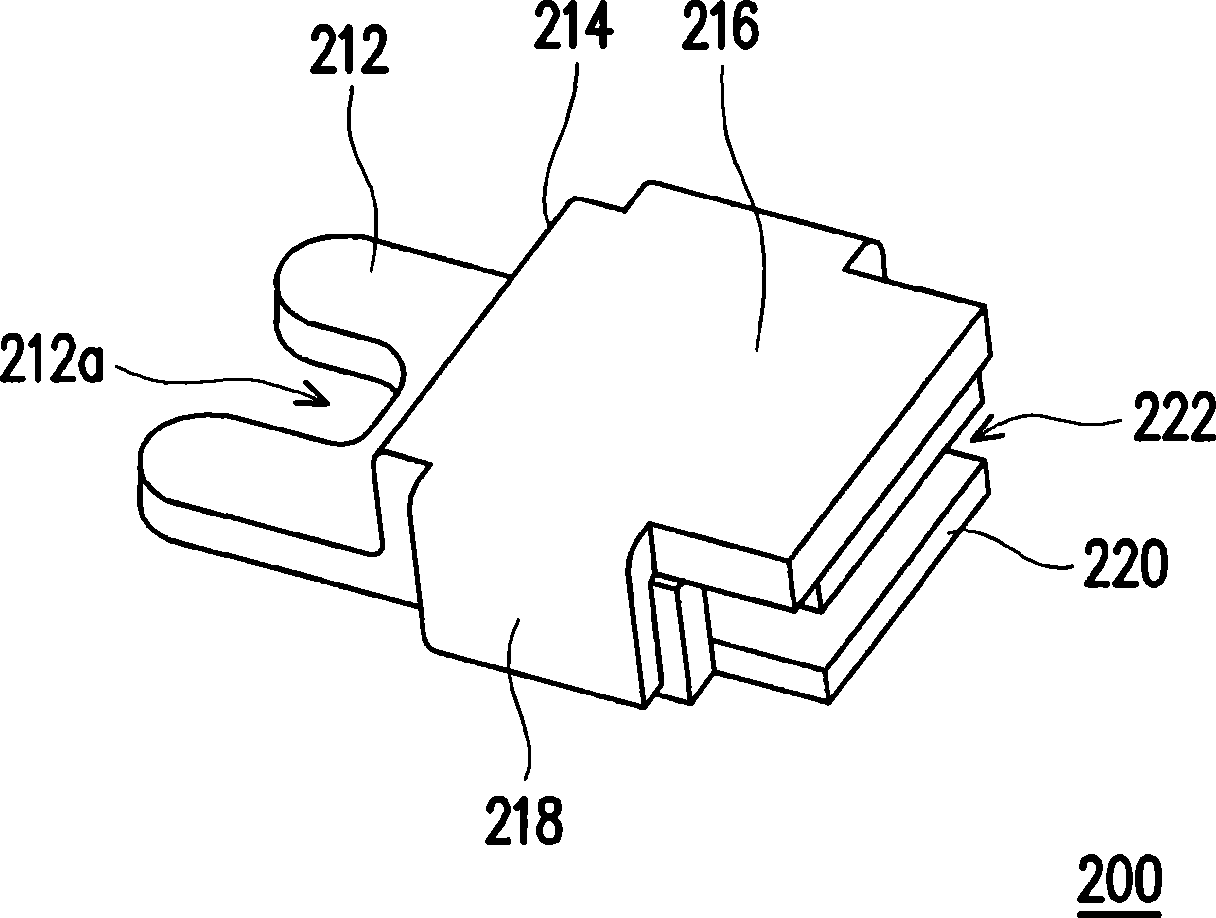
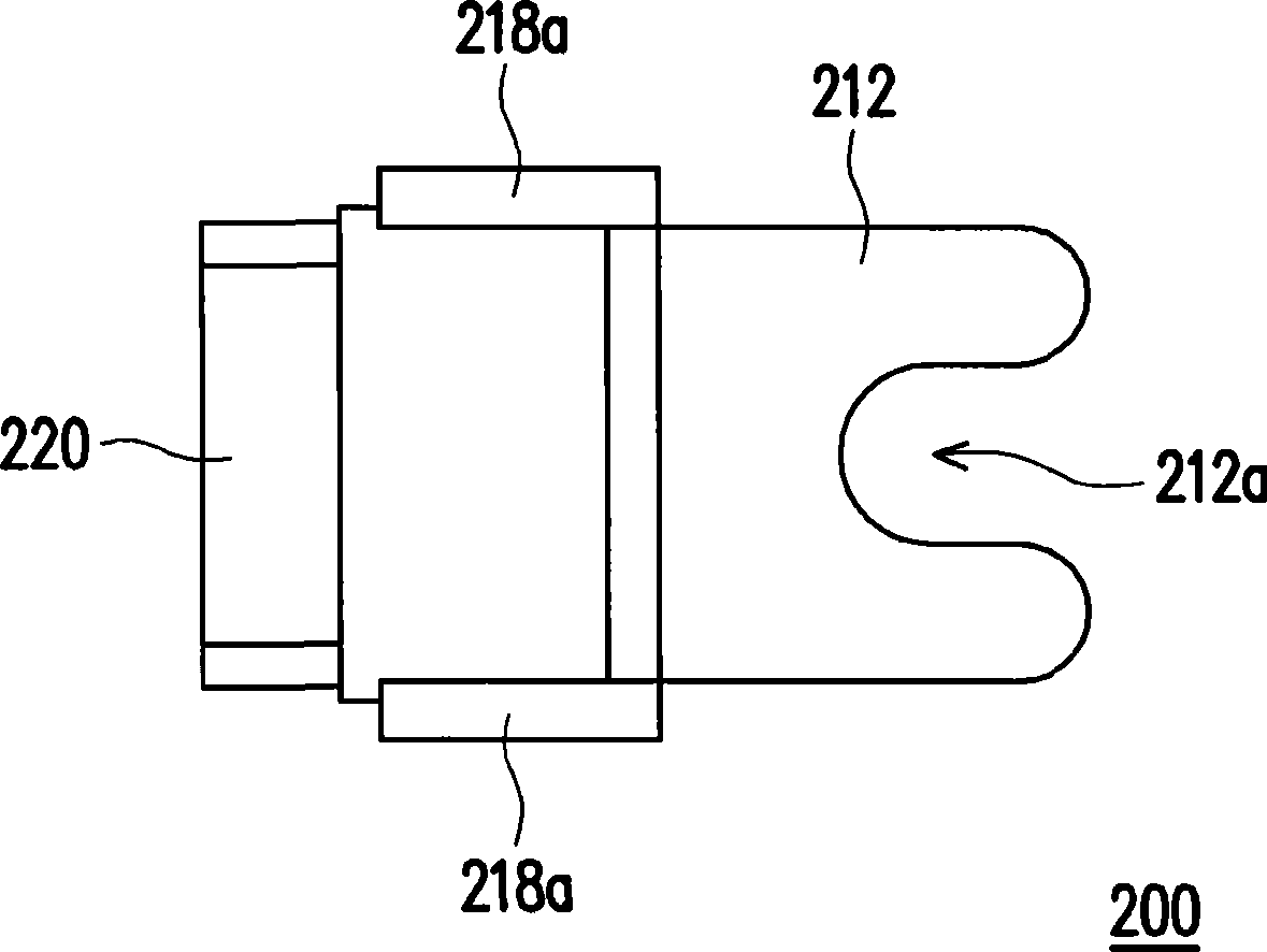
[0018] Figure 2A and Figure 2B It is a top view and a bottom view schematic diagram of a vibration isolation lap joint device according to an embodiment of the present invention, and image 3 It is a schematic diagram of the partial structure of the first structure and the second structure of the vibration isolation lap joint device in FIG. 2 . The vibration isolation lapping device 200 includes a lapping sleeve 210 and a vibration isolator 220 for fixing the first structure 230 on the second structure 240 . The lap sleeve 210 has a lower plate portion 212 , a vertical wall 214 , an upper plate portion 216 and two side plate portions 218 . The lower plate portion 212 has a notch 212 a, and the vertical wall 214 is connected between the lower plate portion 212 and the upper plate portion 216 . The two side plate portions 218 are connected to the upper plate portion 216 and form a receiving groove for receiving the vibration isolator 220 .

[0019] Please refer to image ...


PUM


Abstract

The invention discloses a vibration isolating lap joint device, which is used to fix a first structure on a second structure. The first structure is provided with a blow hole, and the second structure is provided with a fixed link. The vibration isolating lap joint device comprises a lap joint sleeve and a vibration isolator. The lap joint sleeve is provided with a hypoplastron part, a vertical wall, a head plate part and two lateral plate parts, the hypoplastron part is provided with a notch which is fastened laterally with a link body of the fixed link, the vertical wall is connected between the hypoplastron part and the head plate part, and the two lateral plate parts are connected with the head part to form an accommodating groove. The vibration isolator is arranged in the accommodating groove, and is provided with a hollow part which is connected with a convex part inside a blow hole, wherein the lap joint sleeve and the fixed link are accommodated in the blow hole, and the first structure and the second structure are separated for one space by the vibration isolator.

Description

technical field [0001] The present invention relates to a lap joint structure, and in particular to a vibration-isolation lap joint structure. Background technique [0002] In order to improve the utilization efficiency of the internal space of general information appliances or consumer electronics products, screws or screw-free overlapping structures are often used to fix an electronic component on the circuit board. The problem encountered in the method of screw fixing is that in the routine circuit board assembly and debugging procedures in the production process of electronic products, or in the case of disassembly, assembly and replacement of damaged components in subsequent maintenance services , It is often necessary to continuously disassemble or lock the screws. Such repeated actions are too cumbersome and seriously affect the efficiency of production or maintenance operations. [0003] The screw-free overlapping structure overcomes the shortcomings of screw fixing...

Claims


Application Information

Patent Timeline
Patent Type & Authority Applications(China)
IPC IPC(8): H05K7/02
Inventor 蔡协良
Owner INVENTEC CORP
Why Eureka
Try Eureka