Thermoelectric generator with micro-electrostatic energy converter

A technology for thermoelectric generators and electrostatics, applied in the direction of electrochemical generators, thermoelectric device junction lead materials, thermoelectric devices that only use the Peltier or Seebeck effect, etc.

Inactive Publication Date: 2009-06-10
DIGITAL ANGEL CORP
View PDF2 Cites 15 Cited by
  • Summary
  • Abstract
  • Description
  • Claims
  • Application Information

AI Technical Summary

Problems solved by technology

Unfortunately, electrostatic converters have a disadvantage not found in other aforementioned mechanical energy converters

Method used


Image

  • Thermoelectric generator with micro-electrostatic energy converter
  • Thermoelectric generator with micro-electrostatic energy converter
  • Thermoelectric generator with micro-electrostatic energy converter

Examples


Embodiment Construction

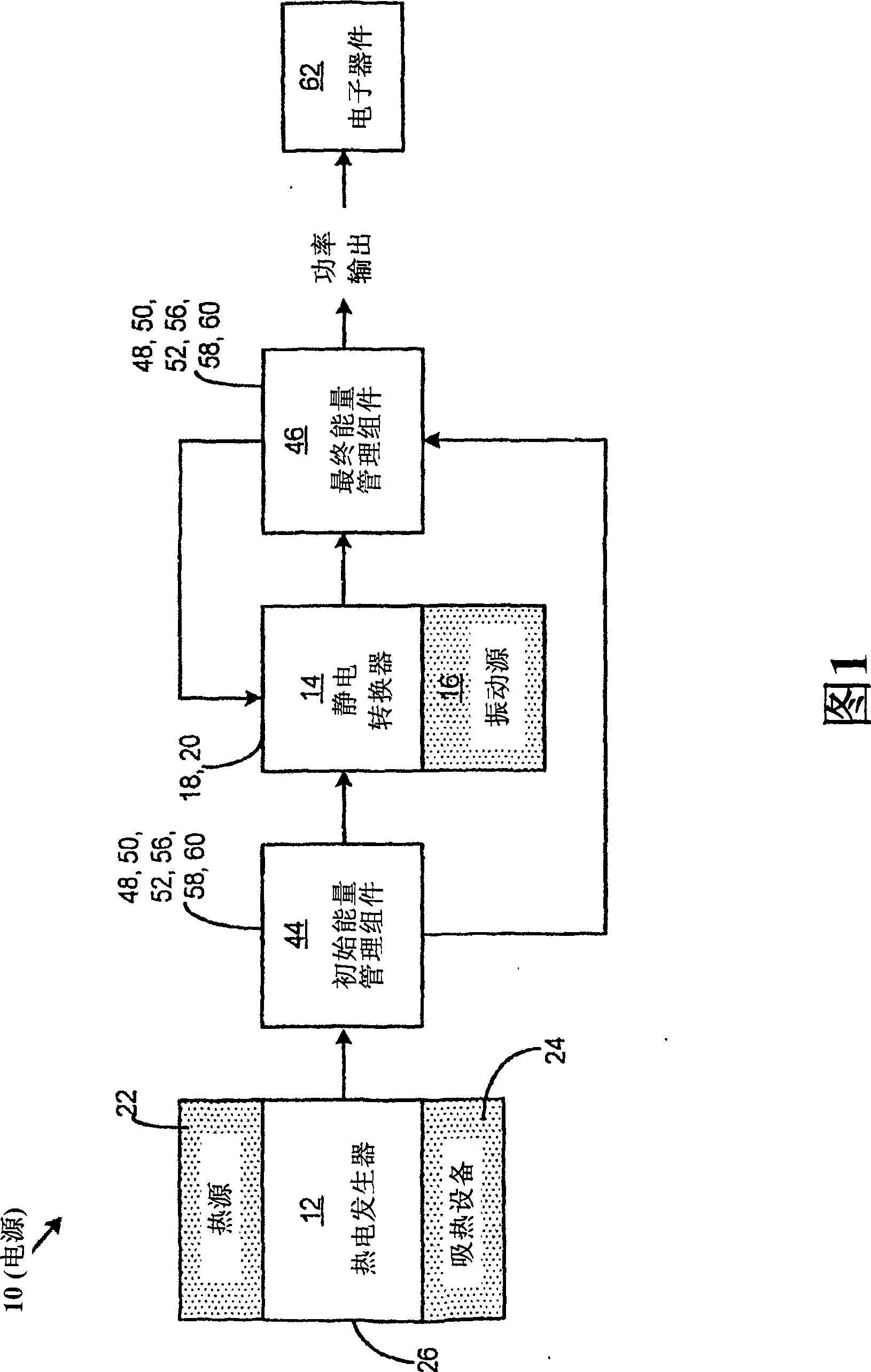
[0025] Reference is now made to the drawings, which are used to illustrate preferred embodiments of the invention and not to modify the invention. As shown in FIG. 1 , it is a schematic diagram of a power source 10 specifically for converting mechanical energy into electrical energy. Advantageously, the power supply 10 of the present invention is used to generate a relatively stable and continuous electrical power supply sufficient for the power required by microelectronic devices and sensor systems.

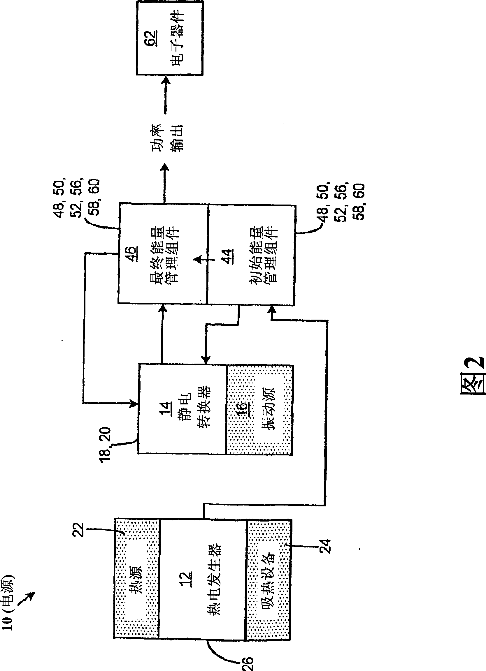
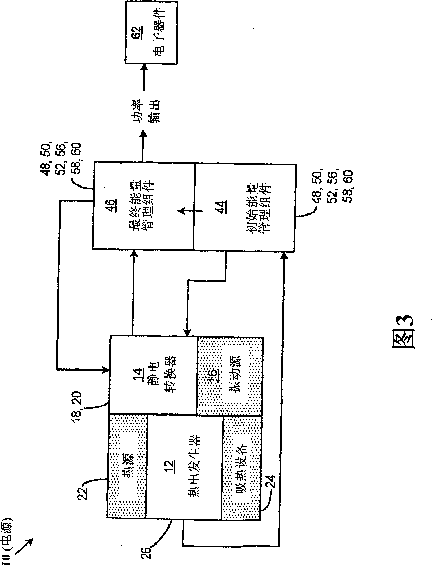
[0026] In the broadest sense, the power supply 10 includes a thermoelectric generator 12 , an initial energy management component 44 , an electrostatic converter 14 and a final energy management component 46 . The thermoelectric generator 12 is used to generate electrical activation energy of a sufficiently high voltage in response to a temperature gradient acting across the thermoelectric generator 12; an initial energy management assembly 44 is connected to the thermoelectric ...


PUM


Abstract

A power supply comprises a thermoelectric generator, an initial energy management assembly, an electrostatic converter and a final energy management assembly. The thermoelectric generator is adapted to generate an electrical activation energy with sufficiently high voltage in response to a temperature gradient acting across the thermoelectric generator. The initial energy management assembly is connected to the thermoelectric generator and is adapted to receive and condition the electrical activation energy produced by the thermoelectric generator. The electrostatic converter is connected to the initial energy management assembly and is activatable by the electrical activation energy received therefrom and is configured to generate electrical energy in response to vibrational energy acting thereupon. The final energy management assembly is connected to the electrostatic converter and is adapted to condition the electrical energy produced thereby.

Description

[0001] CROSS-REFERENCE TO RELATED APPLICATIONS [0002] This application claims priority to co-pending US Provisional Application No. 60 / 809,479, entitled "Thermoelectric Generator with Micro-Electrostatic Transducer," filed May 31, 2006, the entire contents of which are incorporated by reference in their entirety. in this application. This application is also related to US Patent Application No. 11 / 352,113, filed February 10, 2006, entitled "Improved Low Power Thermoelectric Generator," which is US Application No. 11 / 185,312, filed November 7, 2005 A continuation-in-part of the application entitled "Low Power Thermoelectric Generator" which in turn is the current US Patent No. entitled "Low Power Thermoelectric Generator", filed on May 19, 2003, US Application No. 10 / 440,992 is a continuation application of 6,958,443, the entire contents of which are incorporated herein by reference. [0003] Disclaimer: Not Federally Sponsored Research / Development technical field [0004]...

Claims


Application Information

Patent Timeline
IPC IPC(8): H01L35/28H01L35/20H01L35/30H01M10/46
Inventor 英戈·斯达克
Owner DIGITAL ANGEL CORP
Why Eureka
Try Eureka