Gear missing prevention device for rotary tillage rake

A technology of rotary tillage harrow and reverse gear, which is applied in the direction of transmission control, components with teeth, belts/chains/gears, etc., and can solve the problems of increasing the width of the rotary tillage harrow, easily damaged tooth angles, and large noise , to achieve the effect of prolonging the working life, improving safety performance and eliminating noise

Inactive Publication Date: 2009-06-17
王井四
View PDF0 Cites 1 Cited by
  • Summary
  • Abstract
  • Description
  • Claims
  • Application Information

AI Technical Summary

Problems solved by technology

However, in order to improve the working efficiency of the rotary tiller, people often increase the width of the rotary tiller as much as possible. The reality caused is that even if the rotary tiller is in the working state, sometimes there will be a reverse disorder Phenomenon
When the rotary cultivator is out of gear, the disordered collision between the gears will not only make a lot of noise, but also easily damage the tooth corners, so the gears must be repaired and replaced frequently

Method used


Image

  • Gear missing prevention device for rotary tillage rake

Examples


Embodiment Construction

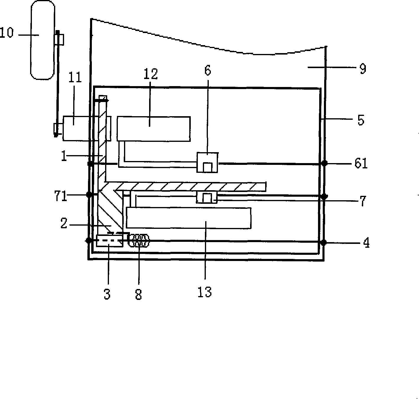
[0014] As shown in the figure, the present invention is mainly composed of a limit pressure rod 1, a limit plate 2, a rotating sleeve 3, and a fixed shaft 4, and is placed in a fixed box 5. During installation, as long as the working gear shift fork shaft 61 and the reverse gear shift fork shaft 71 are taken off, the fixed box can be put into the gearbox, and then the shift fork shaft is installed to the original position through the left and right walls of the fixed box. The limit pressure rod is arranged between the shift fork 6 of the working gear of the gearbox and the shift fork 7 of the reverse gear. In the figure, the limit pressure bar is in the shape of a right-angle turn, wherein the parallel right-angle bar 11 is parallel to the left and right frames of the fixed box, and is flexibly connected with the left frame, and the right-angle bar 12 perpendicular to the parallel right-angle bar is along the reverse gear The shift fork 7 upper openings are arranged; one end o...


PUM


Abstract

The invention relates to a rotary tillage harrow disorder gear resistance device. The device is arranged in the speed changer of a tractor, which mainly comprises a fixing box, a spacing press rod, a spacing plate, a rotary sleeve and a fixing shaft, wherein the spacing press rod is arranged between the shifting forks of the working gear and the reverse gear of a gear box, the fixing shaft is connected to both lateral walls of the box body of the gear box, the rotary sleeve is sheathed outside the shaft, and the spacing plate is connected between the spacing press rod and the rotary sleeve. The invention realizes the work state of no disorder gear during the operation of the rotary tillage of a rotary tillage harrow, and improves the safety performance of a rotary tillage harrow; the invention prolongs the service life of parts of a rotary tillage, and eliminates noise generated during disorder gear; moreover, the device has the advantages of simple structure, no need of changing the arrangement of other assemblies of the gear box, and convenient assembly and disassembly, and the device can be installed on both new tractors and old tractors. Moreover, the invention does not need changing the operation habits of operators, is popular among operators, and can be popularized easily.

Description

technical field [0001] The invention relates to a rotary cultivator driven by a tractor, in particular to a device for preventing disorderly blocking of a rotary cultivator. Background technique [0002] The rotary tiller driven by tractor is an important machinery for agricultural cultivation and is widely used. The rotary tiller has played a positive role in the efficient increase of agricultural production. The rotary cultivator works through the power obtained by meshing the gears of the clutch with the gears of different gears in the gearbox of the tractor. Therefore, under normal circumstances, the shift handle is controlled to complete the gear at a specific position by controlling the different shift forks in the gearbox. The meshing with the clutch gear realizes the working state of rotary tillage and stop of the rotary tiller. However, in order to improve the working efficiency of the rotary tiller, people often increase the width of the rotary tiller as much as p...

Claims


Application Information

Patent Timeline
Patent Type & Authority Applications(China)
IPC IPC(8): F16H63/34F16H61/22
Inventor 王井四
Owner 王井四
Why Eureka
Try Eureka