Ultrasonic ranging method and system thereof

A distance measurement method and technology of a distance measurement system, applied in radio wave measurement systems, sound wave reradiation, measurement devices, etc., can solve problems such as inability to measure accurately, and achieve reduced measurement blind spots, shortened distances, and free oscillation maintenance short time effect

Inactive Publication Date: 2011-06-01
SOUTH CHINA NORMAL UNIVERSITY
View PDF0 Cites 0 Cited by
  • Summary
  • Abstract
  • Description
  • Claims
  • Application Information

AI Technical Summary

Problems solved by technology

For the distance below 40cm, the existing ultrasonic rangefinder cannot be accurately measured

Method used


Image

  • Ultrasonic ranging method and system thereof
  • Ultrasonic ranging method and system thereof
  • Ultrasonic ranging method and system thereof

Examples


Embodiment Construction

[0024] The present invention will be further described below in conjunction with accompanying drawing.

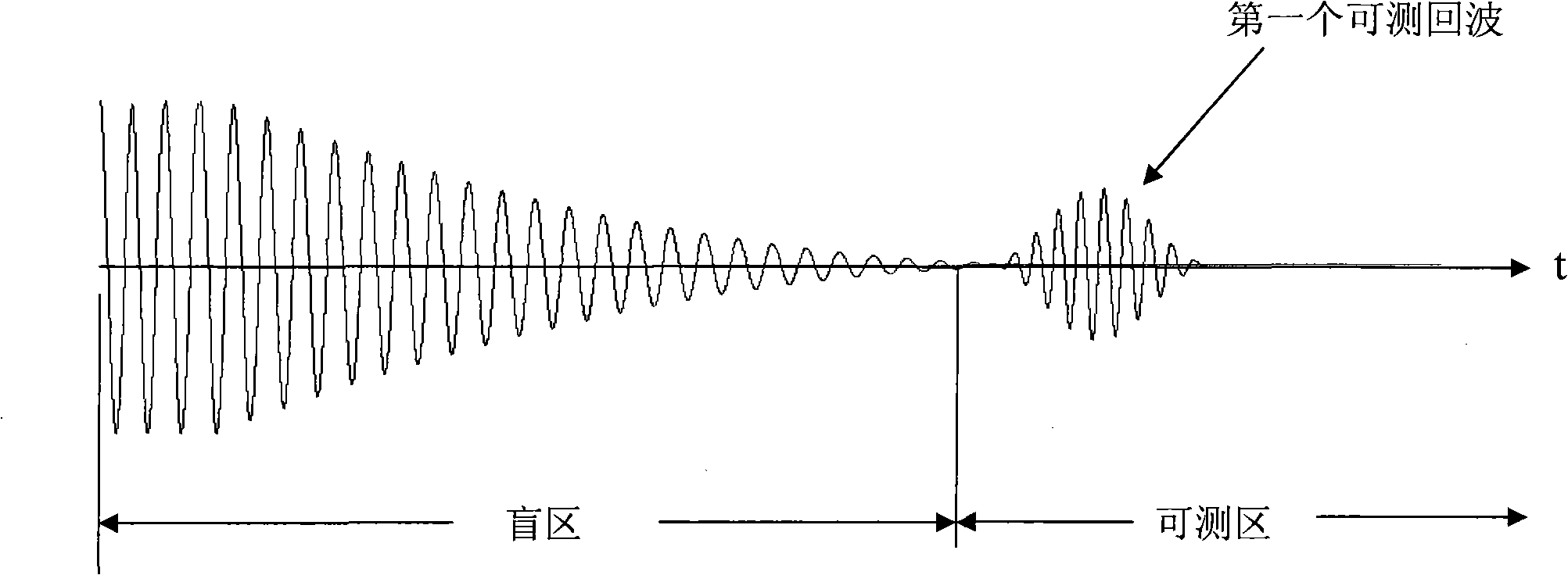
[0025] From image 3 , Figure 4 The comparison shows that when the ultrasonic probe works in a non-resonant mode, the measurement blind area caused by free oscillation is significantly reduced, and the distance of the measurable object is shorter than that of the conventional method.

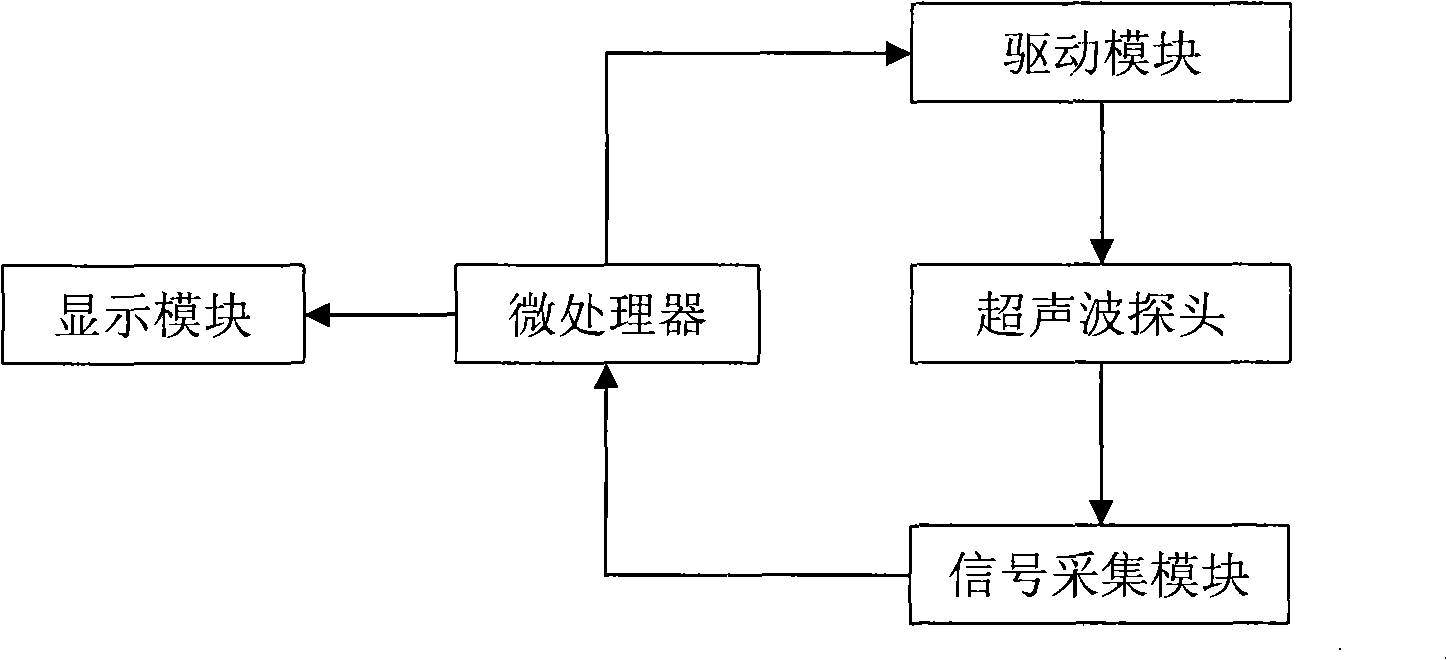
[0026] According to the principles of the present invention, the following scheme can be used to realize the ultrasonic distance measuring system in the small blind zone. Such as figure 1 As shown, an ultrasonic ranging system includes an ultrasonic probe, a microprocessor, a drive module, a signal acquisition module and a display module, the microprocessor is connected to the display module, the display module is mainly used to display the measurement results, and the microprocessor outputs pulses Serial to the drive module, the drive module generates a drive signal to drive the ultrason...


PUM


Abstract

The invention belongs to the technical field of electronic measurement and discloses a method for ultrasonic ranging and a system thereof. The ultrasonic ranging method comprises the following steps: a first threshold value is set; when the distance of the measured object is larger than the threshold value, a resonance operation mode is adopted to drive an ultrasonic probe; when the distance of the measured object is smaller than the threshold value, the driving signal frequency which is applied on the ultrasonic probe deviate from the resonance frequency of the signal. The invention also discloses an ultrasonic ranging system which adopts the method, comprising an ultrasonic probe, a microprocessor, a driver module, a signal acquisition module and a signal display module. Compared with the prior art, the invention can greatly reduce a measurement blind area from the known 40cm to below 10cm.

Description

technical field [0001] The invention relates to the technical field of electronic measurement, in particular to an ultrasonic distance measuring method and a system thereof. Background technique [0002] Ultrasonic ranging has been widely used, and the measurement accuracy is getting higher and higher. However, for the ultrasonic ranging method currently used, when the measured object is very close to the ultrasonic probe (about a few centimeters), the distance of the measured object The reflected wave will reach the probe before the free oscillation of the ultrasonic probe ends, so there are two signals on the ultrasonic probe at the same time: one is the signal due to free oscillation, the other is the signal reflected by the measured object, and the two signals interfere with each other. As a result, the receiving circuit of the ranging system cannot judge the position of the actual reflected wave in the signal. Generally, the distance corresponding to the free oscillati...

Claims


Application Information

Patent Timeline
Patent Type & Authority Patents(China)
IPC IPC(8): G01S7/523G01S15/08
Inventor 周卫星秦笛
Owner SOUTH CHINA NORMAL UNIVERSITY
Why Eureka
Try Eureka