Method for forming a tilting zone on a transverse element for a push belt for a continuously variable transmission

A technology of continuously variable transmission and transverse elements, applied in the direction of household elements, belts, V-shaped belts, etc., can solve the problems of unreached pressure level, danger, deviation of the shape of the inclined area, etc., and achieve good repeatability

Active Publication Date: 2009-06-17
ROBERT BOSCH GMBH
View PDF0 Cites 2 Cited by
  • Summary
  • Abstract
  • Description
  • Claims
  • Application Information

AI Technical Summary

Problems solved by technology

In fact, there is a clear risk that the required pressure level is not achieved and that the concave part of the surface of the transverse element is not accurately set in the surface of the transverse element's body, whereby the resulting oblique area of The shape deviates from the defined shape

Method used


Image

  • Method for forming a tilting zone on a transverse element for a push belt for a continuously variable transmission
  • Method for forming a tilting zone on a transverse element for a push belt for a continuously variable transmission
  • Method for forming a tilting zone on a transverse element for a push belt for a continuously variable transmission

Examples


Embodiment Construction

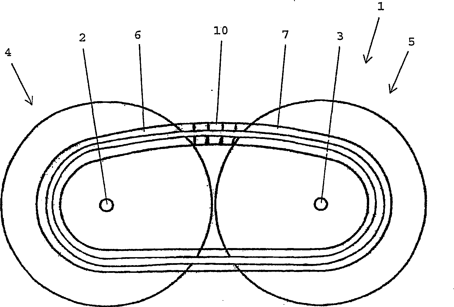
[0029] figure 1A continuously variable transmission is shown schematically, which is especially suitable for use in a motor vehicle. The continuously variable transmission is indicated generally by the reference numeral 1 .

[0030] The continuously variable transmission 1 comprises two pulleys 4 , 5 which are arranged on separate pulley shafts 2 , 3 . A continuous push belt 6 shaped as a closed loop is arranged around the pulleys 4 , 5 and serves to transmit torque between the pulley shafts 2 , 3 . Each pulley 4, 5 comprises two pulley sheaves (pulley sheave), wherein said pulley 6 is located and sandwiched between said two pulley sheaves, so that the force can be between the pulleys 4, 5 and The push belts 6 are transmitted by friction.

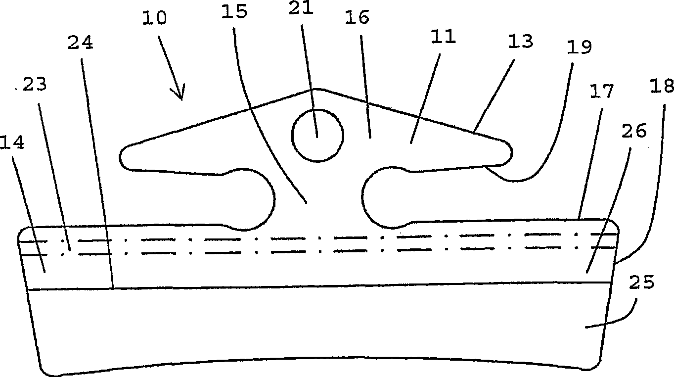
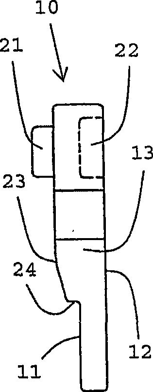
[0031] The push belt 6 comprises at least one continuous carrier 7 substantially comprising a plurality of loops. Transverse elements 10 are arranged along the entire length of the carrier 7 , each transverse element 10 being adjacent t...


PUM


Abstract

A method for forming a convex tilting zone (23) at a main body- surface (11) of a transverse element for application in a push bel for a continuously variable transmission comprises the step of applying a die (30) that is placed against the main body surface (11) under pressure. However, the die (30) is pressed against the main body surface (11) just outside of an area where the tilting zone (23)needs to be formed. By applying the die (30), a recessed area (27) is arranged in the main body surface (11), wherein retraction of the material of the transverse element takes place along an upper edge (28) of this area (27). A retraction area that is obtained in this manner is suitable to function as tilting zone (23). An important advantage of the application of the described method is that the pressure that is exerted on the die (30) may be considerably lower than the pressure that is required during conventional processes for forming a tilting zone (23).

Description

technical field [0001] The invention relates to a method of forming a convexly sloped area in a defined area of ​​the body surface of a transverse element provided as part of a push belt of a continuously variable transmission comprising two suspensions for The pulley of said push belt, wherein the tool element is pressed against the body surface of the transverse element, thereby effecting movement of material on the body surface. Background technique [0002] Push belts for continuously variable transmissions are generally known. Typically, such push belts consist of two continuous, belt-shaped carriers shaped like closed loops in order to carry a relatively large number of transverse elements. The transverse elements are arranged along the entire periphery of the carrier, wherein during operation the transverse elements can transmit the forces associated with the movement of the push belt. Both the carrier and the transverse element are made of metal. [0003] In the f...

Claims


Application Information

Patent Timeline
Patent Type & Authority Applications(China)
IPC IPC(8): B21D53/14F16G5/16
CPCF16G5/16B21K23/00B21D53/14
Inventor L·H·M·普林森
Owner ROBERT BOSCH GMBH
Why Eureka
Try Eureka