Engine generating set utilizing kinetic energy and wind energy

A power generation device and wind energy technology, applied in electromechanical devices, motors, electric vehicles, etc., can solve the problems of power that cannot output large energy, small motors, and low power.

Inactive Publication Date: 2009-06-24
朱仕亮
View PDF0 Cites 1 Cited by
  • Summary
  • Abstract
  • Description
  • Claims
  • Application Information

AI Technical Summary

Problems solved by technology

In order to save energy, some means of transportation are also equipped with small generators. For example, in order to ensure the start of the engine and the sufficient power of the battery in a car, the engine is equipped with a small generator through a belt drive to drive the generator to generate electricity when the car is moving at high speed. , to charge the battery, but this kind of generator is often a small model with low power generation, which can only supplement the battery, and cannot output large energy to play a grea...

Method used


Image

  • Engine generating set utilizing kinetic energy and wind energy
  • Engine generating set utilizing kinetic energy and wind energy
  • Engine generating set utilizing kinetic energy and wind energy

Examples


Embodiment 1

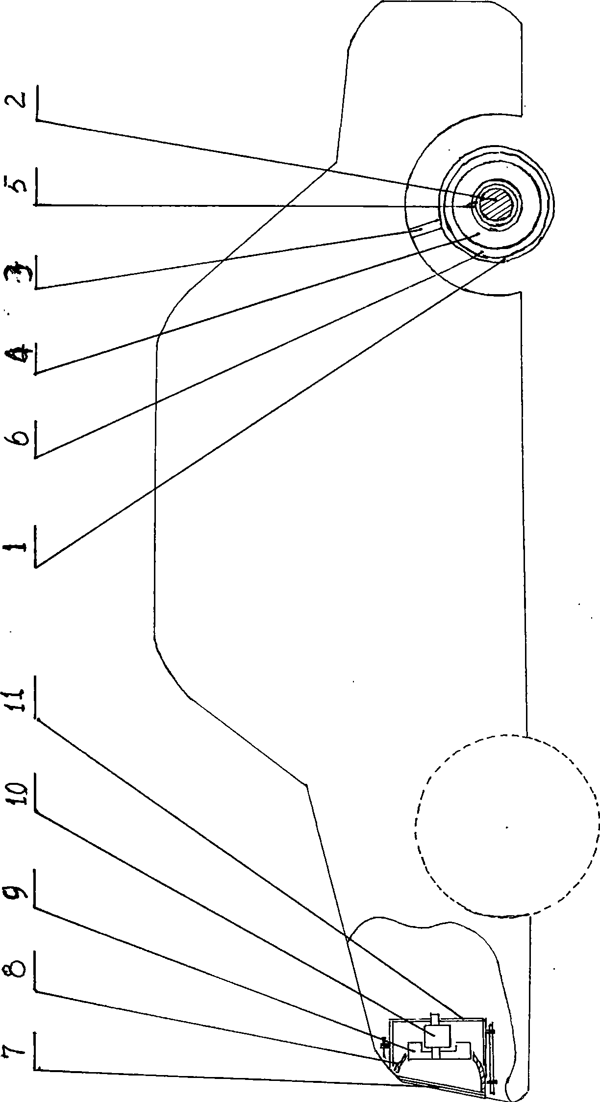
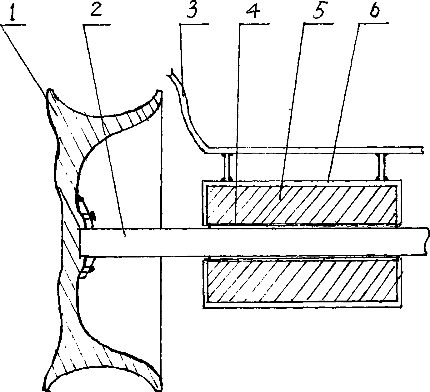
[0013] Example 1, see figure 1 , figure 2 , a motorized power generation device using kinetic energy and wind energy is composed of a hub 1, a wheel shaft 2, a stator coil 4, a rotor coil 5, a fan impeller 9, a generator 10, etc., and the stator coil is embedded in a stator 6 fixed on a support plate 3 On a neutral or non-rotating wheel shaft, the rotor coil is fixed on the wheel hub or the wheel shaft to form magnetic cutting and generate current. A fairing 8 is fixed behind the center grid 7 of the front of the car, and a fan impeller and a generator are installed behind the fairing. The generator is installed on bracket 11.

Embodiment 2

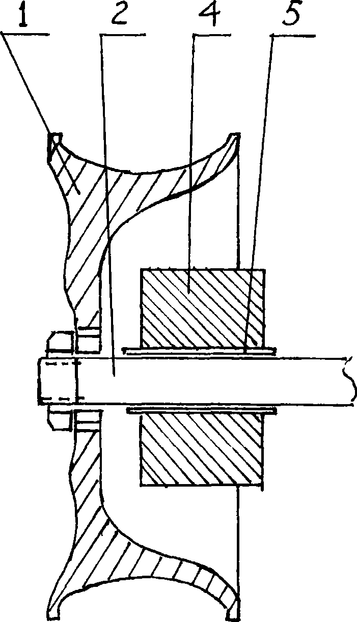
[0014] Example 2, see figure 1 , figure 2 , image 3 , a motorized power generation device using kinetic energy and wind energy is composed of a hub 1, a wheel shaft 2, a stator coil 4, a rotor coil 5, a fan impeller 9, a generator 10, etc., and the stator coil is embedded in a stator 6 fixed on a support plate 3 On a neutral or non-rotating wheel shaft, the rotor coil is fixed on the wheel hub or the wheel shaft to form magnetic cutting and generate current. A fairing 8 is fixed behind the center grid 7 of the front of the car, and a fan impeller and a generator are installed behind the fairing. The generator is installed On the bracket 11, the rotor coil of this embodiment is composed of multiple pieces of permanent magnets.

Embodiment 3

[0015] Example 3, see figure 1 , figure 2 , image 3 , a motorized power generation device using kinetic energy and wind energy is composed of a hub 1, a wheel shaft 2, a stator coil 4, a rotor coil 5, a fan impeller 9, a generator 10, etc., and the stator coil is embedded in a stator 6 fixed on a support plate 3 On a neutral or non-rotating wheel shaft, the rotor coil is fixed on the wheel hub or the wheel shaft to form magnetic cutting and generate current. A fairing 8 is fixed behind the center grid 7 of the front of the car, and a fan impeller and a generator are installed behind the fairing. The generator is installed On the bracket 11, in order to make better use of the rotation of the wheel hub, a fixed plate can be added on the inside of the wheel hub in this implementation, and a circular friction plate is fixed on the plate. The generator with the friction wheel is fixed on the support plate, and the friction wheel In contact with the friction plate, the generator...


PUM


Abstract

The invention discloses an engine driven generating set utilizing kinetic energy and wind energy, which consists of a hub (1), a wheel shaft (2), a stator coil (4), a rotor coil (5), a fan impeller (9), a motor (10), and so on, and is characterized in that the stator coil is embedded in a stator (6) which is fixed on a bearing plate (3) or embedded on the fixed wheel shaft; the rotor coil is fixedly connected to the hub or the wheel shaft to form magnetic force cutting to generate current; a cowling (8) is arranged on the rear of a headstock middle net (7); the fan impeller and the motor are arranged on the rear of the cowling; and the motor is arranged on a support (11). The engine driven generating set is also provided with the motor, when a vehicle runs, the motor is rotated under the action of air intake to generate electrical power to charge a vehicle storage battery, so the engine driven generating set can provide sizable electrical power to drive the vehicle.

Description

technical field [0001] The invention relates to a power generation device, in particular to a motorized power generation device utilizing kinetic energy and wind energy. Background technique [0002] As everyone knows, people have been using various energy sources as power generation for a long time. In order to save energy, some means of transportation are also equipped with small generators. For example, in order to ensure the start of the engine and the sufficient power of the battery in a car, the engine is equipped with a small generator through a belt drive to drive the generator to generate electricity when the car is moving at high speed. , to charge the storage battery, but this kind of generator is often a small model with low power generation, and can only supplement the storage battery, and cannot output power with greater energy to play a greater role. In addition, there are people who utilize the rotational kinetic energy on the rotating wheel shaft of the bic...

Claims


Application Information

Patent Timeline
IPC IPC(8): B60L8/00B60L11/00H02K7/18
CPCY02T10/7083Y02T10/641Y02T10/64Y02T10/7072
Inventor 朱仕亮
Owner 朱仕亮
Why Eureka
Try Eureka