Splicer nozzle

A splicer and nozzle technology, applied in the field of splicer nozzles, can solve problems such as residues and appearance problems, and achieve the effect of improving the strength of the joint

Active Publication Date: 2009-06-24
MURATA MASCH LTD
View PDF6 Cites 14 Cited by
  • Summary
  • Abstract
  • Description
  • Claims
  • Application Information

AI Technical Summary

Problems solved by technology

However, if a T-type splicer is used, as in Japanese Patent Application Publication No. 2006-52485 Figure 4 As shown, since the yarn Y1 and the yarn Y2 form a "T" shape in which the overlapped part is a vert

Method used


Image

  • Splicer nozzle
  • Splicer nozzle
  • Splicer nozzle

Examples


Embodiment Construction

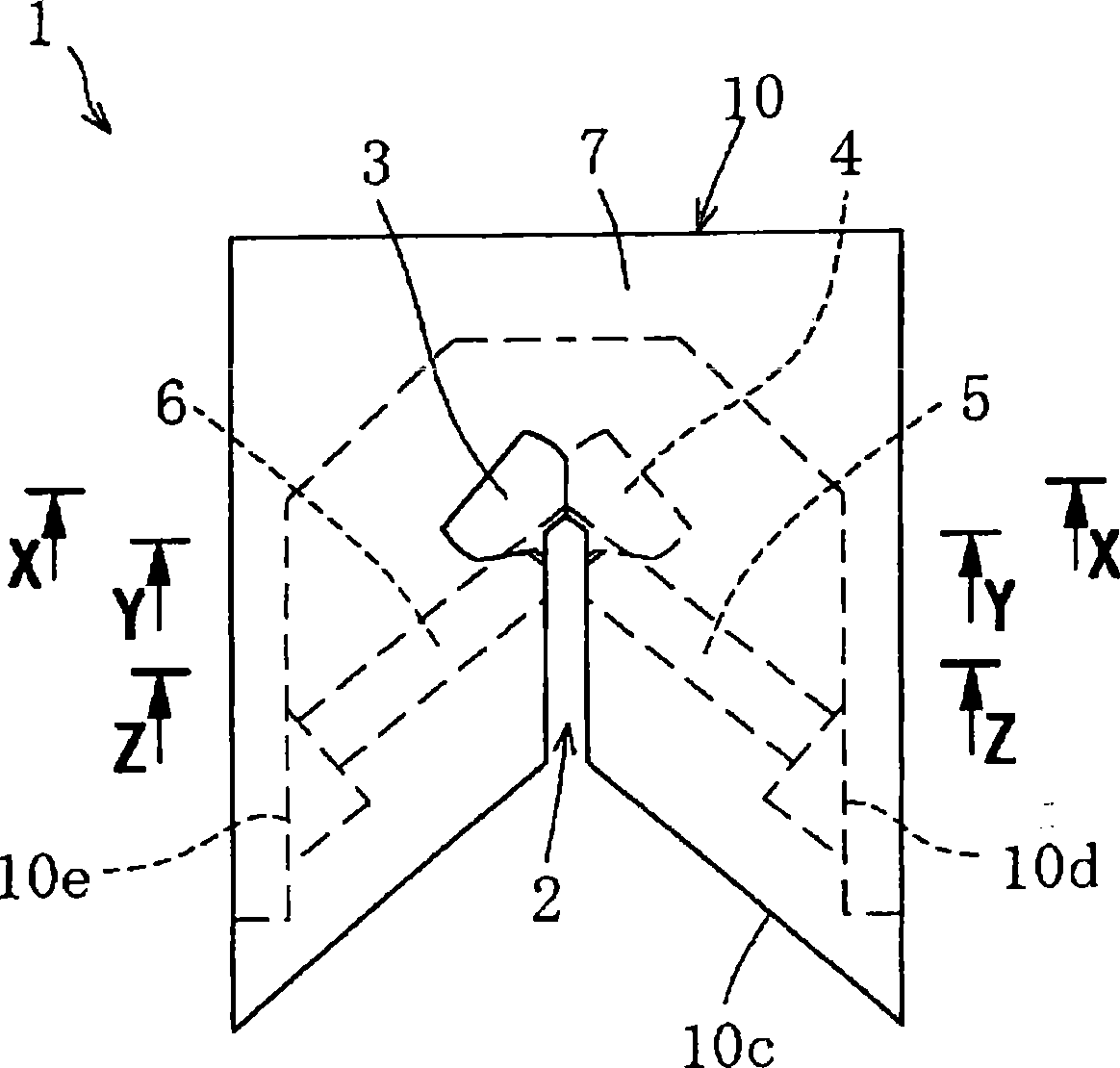
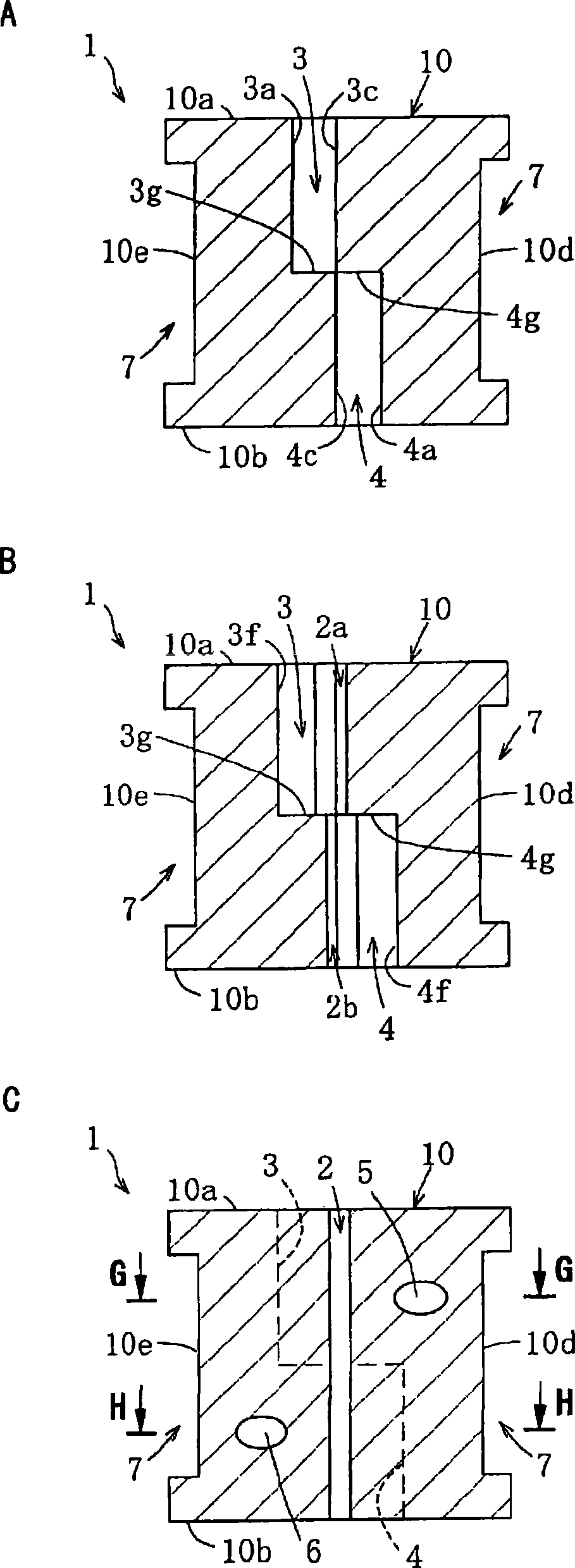
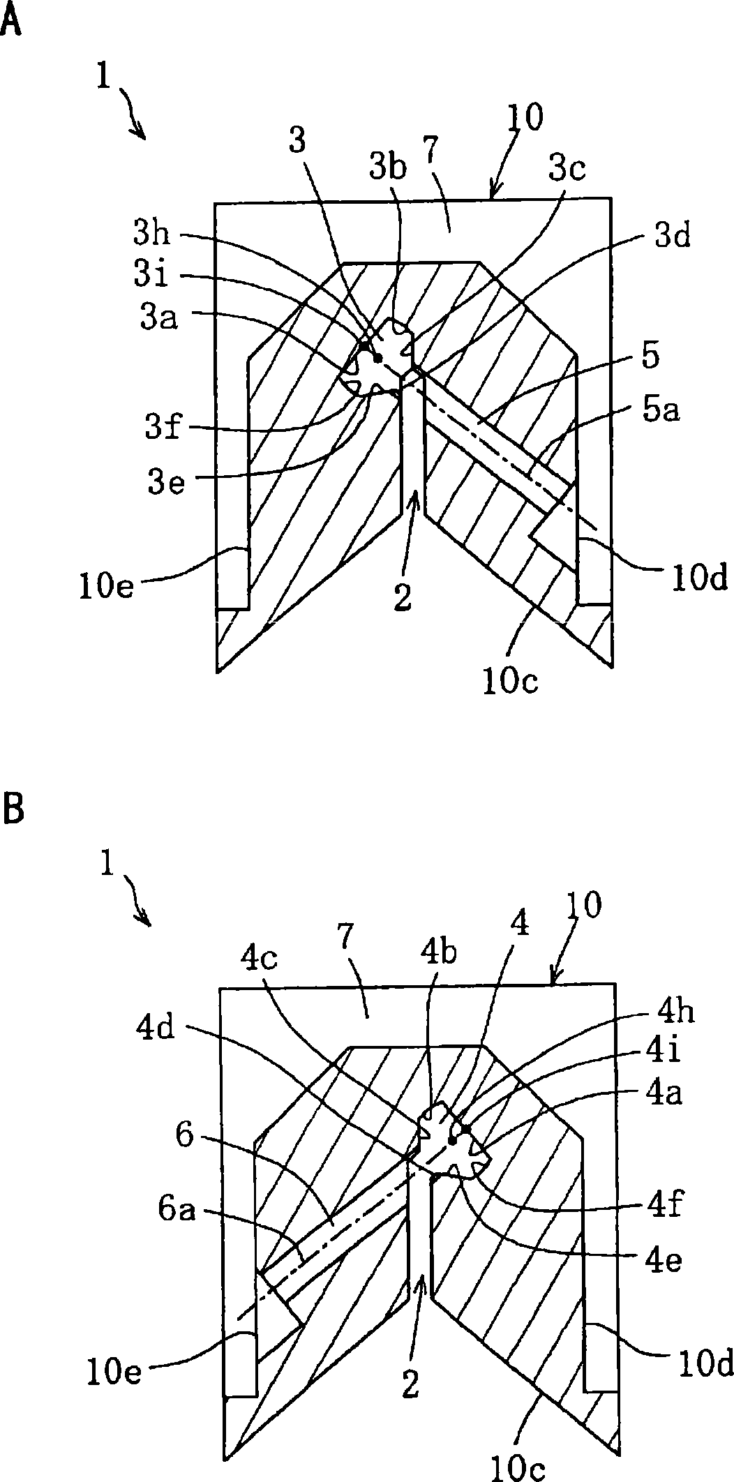
[0022] A preferred embodiment of the present invention will be described below with reference to the accompanying drawings. figure 1 It is a plan view showing an example of the splicer nozzle of the present invention, figure 2 for figure 1 The cross-sectional view of the splicer nozzle, (A) is a cross-sectional view along the X-X line, (B) is a cross-sectional view along the Y-Y line, and (C) is a cross-sectional view along the Z-Z line. image 3 for figure 1 (A) is a cross-sectional view along line G-G, and (B) is a cross-sectional view along line H-H. Figure 4 used to represent figure 1 A perspective view of an example of a splicer nozzle assembly of a splicer nozzle, Figure 5 It is a sectional view showing the relationship between the splicer nozzle and the splicer nozzle assembly.

[0023] [Splitter Nozzle Configuration]

[0024] Such as Figure 1 ~ Figure 3 As shown, the splicer nozzle 1 of the present invention is mainly composed of the following parts: the ...


PUM


Abstract

The present invention provides a splicer nozzle (1) characterized in that a yarn splicing hole is divided, in an axial direction, into substantially two yarn splicing chambers (3, 4) formed at positions where axes (3h, 4h) of the yarn splicing chambers (3, 4) are displaced from each other, and a yarn splicing slit (2) common to the yarn splicing chambers (3, 4) is formed over the entire area of the yarn splicing hole, and in that an injection hole (5, 6) is formed for each of the yarn splicing chambers (3, 4) so that compressed air passing through the yarn splicing slit (2) to the axis (3h), (4h) of the yarn splicing chamber (3, 4) is injected through a corresponding one of the injection holes (5, 6), and an inner wall (3a, 4a) of each of the yarn splicing chambers (3, 4) located oppositean air outlet of the corresponding one of the compressed air injection holes (5, 6) is formed to be planar.

Description

technical field [0001] The present invention relates to a splicer nozzle for splicing two yarn ends overlapping in opposite directions by jetting compressed air. Background technique [0002] Conventionally, a splicer is known as a piecing device for piecing ends of two yarns. The splicer is a device that blows compressed air to the ends of two overlapping yarns and twists the ends of the two yarns together for jointing. There are two types of the splicer called the opposite type and the T-type. [0003] The opposing splicer untwises the ends of the two yarns, overlaps them in opposite directions, and twists the ends of the two yarns together by twisting backflow generated by compressed air. See, for example, Japanese Patent Application Publication No. 2-14267. [0004] On the other hand, the T-splicer overlaps the ends of two yarns in the same direction, and then uses compressed air to untwist and entangle the ends of the yarns. See, for example, JP-A-2006-52485. [00...

Claims


Application Information

Patent Timeline
IPC IPC(8): D01H15/00
CPCB65H2701/31B65H69/061
Inventor 美马博志
Owner MURATA MASCH LTD
Why Eureka
Try Eureka