Carbon beaverboard anchorage

A carbon fiber board and anchor technology, which is applied in the field of anchors to achieve the effects of sufficient contact, increased friction and high production efficiency

Inactive Publication Date: 2009-06-24
LIUZHOU OVM MASCH CO LTD
View PDF1 Cites 21 Cited by
  • Summary
  • Abstract
  • Description
  • Claims
  • Application Information

AI Technical Summary

Problems solved by technology

[0004] The technical problem to be solved by the present invention is to provide a carbon fiber plate anchor that can make the carbon fiber plate be evenly compressed during the clamping process, has reliable anchoring performance, and has a compact structure and is convenient for manufacture and construction, so as to solve the problem that the carbon fiber plate cannot be reliably anchored. The problem that carbon filaments are easy to be cut, and at the same time overcome the above-mentioned method of bonding and anchoring carbon fiber plates and the shortcomings of the existing "Carbon Fiber Plate Anchors"

Method used


Image

  • Carbon beaverboard anchorage
  • Carbon beaverboard anchorage
  • Carbon beaverboard anchorage

Examples


Embodiment 1

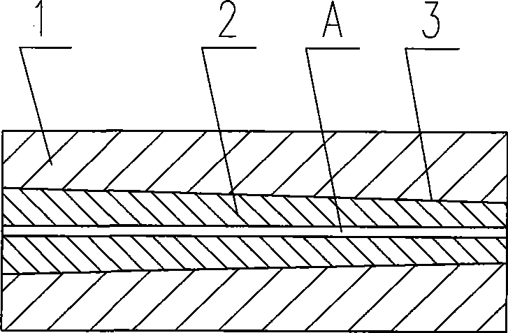
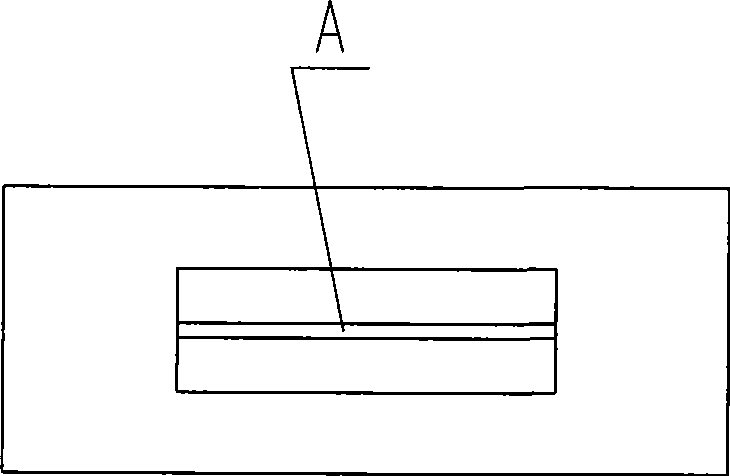
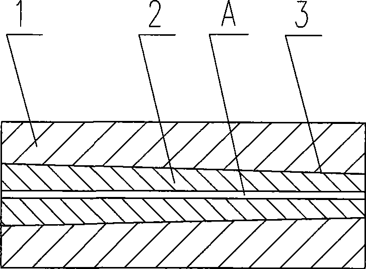
[0035] A carbon fiber plate anchor, the anchor plate 1 is a cylinder with a rectangular cross section, and a wedge-shaped through hole with a rectangular cross section and a tapered longitudinal section is opened inside, and the clip 2 is a two-piece wedge-shaped block , the closed shape after it is wedged into the anchor plate to clamp the carbon fiber plate is closely matched with the wedge-shaped through-hole with a rectangular cross-section and a tapered longitudinal section in the anchor plate (see Figure 1 ~ Figure 2 ).

Embodiment 2

[0037] A carbon fiber plate anchor, the anchor plate 1 is a cylinder with an elliptical cross-section, and a wedge-shaped through-hole with a rectangular cross-section and a taper in the longitudinal section is opened inside, and the clip is a two-piece wedge-shaped block , the closed shape after it is wedged into the anchor plate to clamp the carbon fiber plate is closely matched with the wedge-shaped through-hole with a rectangular cross-section and a tapered longitudinal section in the anchor plate (see Figure 3 ~ Figure 4 ).

Embodiment 3

[0039] A carbon fiber plate anchor, the anchor plate is a cylinder with a circular cross section, and a wedge-shaped through hole with a rectangular cross section and a taper in the longitudinal section is opened inside, and the clip is a two-piece wedge block. The closed shape after it is wedged into the anchor plate to clamp the carbon fiber plate is closely matched with the wedge-shaped through hole with a rectangular cross section and a tapered longitudinal section inside the anchor plate (see Figure 5 ~ Figure 6 ).


PUM


Abstract

The invention relates to an anchorage device, in particular to a carbon fiber plate anchorage device used in civil engineering and building construction. The anchorage device consists of an anchor plate and a clamping piece; the anchor plate is a whole part and is internally provided with a wedged-shape through hole, the clamping piece is a two-piece type wedge block, the clamping piece is wedged into the anchor plate for tightly clamping the carbon fiber plate, then the wedge block is in close fit with the wedged-shape through hole in the anchor plate; the anchor plate is of a cylinder with rectangular or square or elliptic or circular cross section, the anchor plate is internally provided with the wedged-shape through hole with the rectangular or square or elliptic or circular cross section and tapering longitudinal section, and the folding contour formed after the clamping piece is wedged into the anchor plate for tightly clamping the carbon fiber plate is the same as that of the wedged-shape through hole with the rectangular or square or elliptic or circular cross section and tapering longitudinal section in the anchor plate; the clamping face of the clamping piece has a layer of a contact reinforcing material of the carbon fiber plate; and the contact surface of the clamping piece and the anchor plate is coated with lubricating oil or lubricating grease. The anchorage device has the advantages of reliable anchoring property, simple and compact structure, convenient manufacture, construction and operation, high efficiency and various shapes, and the anchorage device can meet the requirement of different construction environments.

Description

Technical field: [0001] The invention relates to an anchor, in particular to a carbon fiber plate anchor used in civil engineering. Background technique: [0002] Carbon fiber plate is a new type of high-strength material, which is usually attached to the surface of concrete components in civil engineering to strengthen the strength of components. If it is pre-tensioned before pasting and then anchored to the surface of the component, the bending strength and crack resistance of the component can be enhanced, and its strength can be fully utilized. Therefore, prestressed carbon fiber reinforced concrete members have obvious advantages over ordinary pasted fiber reinforcement. However, the prestressing reinforcement technology requires tensioning and anchoring of carbon fiber sheets. Although carbon fiber sheets have high tensile strength but low transverse shear strength, it is easy to cut off carbon filaments when clamping and anchoring them, and they will slip if they are...

Claims


Application Information

Patent Timeline
Patent Type & Authority Applications(China)
IPC IPC(8): E04C5/12
Inventor 杨帆朱万旭黄颖庞忠华付委
Owner LIUZHOU OVM MASCH CO LTD
Why Eureka
Try Eureka