
High temperature composite fatigue loading method and apparatus for turbine disc/blade joggled joint

A fatigue loading, turbine blade technology, applied in the aerospace field, can solve the problems of mutual interference between high and low cycle loads, low frequency vibration and small loads are not easily transmitted to the tenon joint, reasonable stress distribution, and difficulty in reproducing the load state. Safe and reliable work, the effect of reducing resistance

Inactive Publication Date: 2009-06-24
BEIHANG UNIV
View PDF0 Cites 58 Cited by
  • Summary
  • Abstract
  • Description
  • Claims
  • Application Information

AI Technical Summary

Problems solved by technology

The problem with the traditional method of applying high-temperature composite loads to the tenon joints of real turbine disks / blades is that when low-frequency centrifugal large loads are applied to the tester, the small loads of high-frequency vibrations are not easily transmitted to the tenon joints smoothly, and reasonable Distributed stress; there is mutual interference between high and low cycle loads at the same time, it is difficult to reproduce the actual load state

Method used


Image

  • High temperature composite fatigue loading method and apparatus for turbine disc/blade joggled joint
  • High temperature composite fatigue loading method and apparatus for turbine disc/blade joggled joint
  • High temperature composite fatigue loading method and apparatus for turbine disc/blade joggled joint

Examples


Embodiment Construction

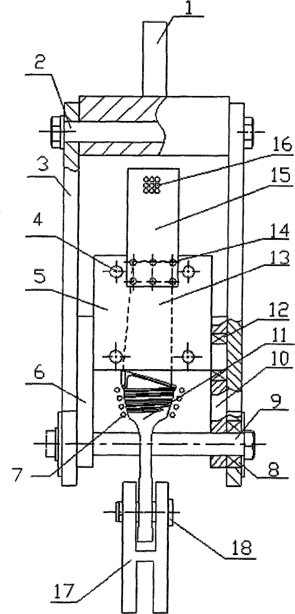
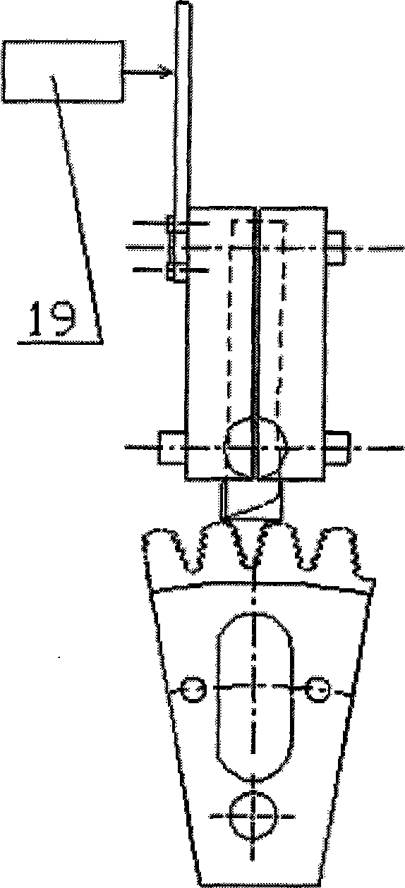
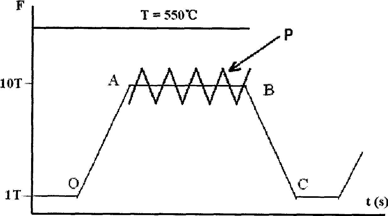
[0025] See figure 1 , figure 2 , image 3 As shown, a turbine disk / blade tenon joint high temperature composite fatigue loading method and device thereof according to the present invention are specifically implemented as follows:

[0026] The present invention is a high-temperature composite fatigue loading device for turbine disc / blade tenon joint. Force top plate 6, high-frequency induction heating ring 7, rolling bearing 8, force transmission round rod 9, right force transmission top plate 10, rolling bearing 12, compression bolt 14, high cycle load transmission plate 15, force mechanism under low cycle load 17, down transmission force pin 18, exciter 19 forms.

[0027]Low cycle load upper force mechanism 1 is connected with force transmission main tension plate 3 through force transmission pin 2; force transmission main tension plate 3 is connected with force transmission round bar 9 through a pair of rolling bearings 8; the lower ends of left and right force transmiss...


PUM


Abstract

A turbine disc / blade tenon connection high-temperature combined fatigue loading device comprises a low cycle load stress application mechanism, a force transmission pin, a force transmission main tension plate, a force transmission crown plate, a force transmission round bar, a blade clamp, a rolling bearing, a hold-down bolt, a high cycle transmission plate, a high-frequency heating cycle, and a vibration generator, wherein, the low cycle load stress application mechanism is connected with the force transmission main tension plate through the force transmission pin; the force transmission main tension plate is connected with the force transmission round bar through the rolling bearing; the lower end of the force transmission crown plate is sleeved on the force transmission round bar, and the upper end is connected with the load bearing dummy club of the blade clamp through the rolling bearing; the blade clamp is connected with the blade of a turbine through the hold-down bolt; the turbine disc is connected with the low cycle load stress application mechanism through the force transmission pin; the high cycle transmission plate is connected with the blade clamp through the hold-down bolt; and the vibration generator is positioned on one side above a high cycle load transmission plate. The loading method is characterized in that the force application point of low cycle loads is moved backwards, thereby enabling small high cycle loads to be smoothly transferred to the tenon connection position, ensuring the stress distribution along the tenon tooth is reasonable, and preventing combined loads from interfering with each other.

Description

(1) Technical field [0001] The invention relates to a loading method and device for aero-engine components, in particular to a high-temperature composite fatigue loading method and device for a turbine disk / blade tenon joint, belonging to the technical field of aerospace. (2) Background technology [0002] Aeroengine turbine disks and turbine blades are usually made of fir-tree joints, and the reliability of the tenon joint structure is the bottleneck that limits the life, safety and reliability of aircraft and engines. The reason is that the mortise groove of the turbine disk / blade mortise teeth is the stress concentration part, which is very prone to cracks. If the crack exceeds the standard, it will be scrapped; The nature of the crack in the mortise joint belongs to the composite fatigue of low-frequency large load (mainly centrifugal force) superimposing high-frequency small load (mainly high-cycle blade bending vibration load) at high temperature. Therefore, using rea...

Claims


Application Information

Patent Timeline
IPC IPC(8): G01N3/32
Inventor 王荣桥胡殿印侯贵仓申秀丽
Owner BEIHANG UNIV
Learn More