
Rectangular aperture telescope antenna of synthetic aperture laser imaging radar

A synthetic aperture laser and rectangular aperture technology, applied in telescopes, optics, optical components, etc., can solve the problems of reduced azimuth resolution, uneven resolution, and inability to control separately, and eliminate the problem of reduced azimuth imaging resolution Effect

Active Publication Date: 2011-07-13
SHANGHAI INST OF OPTICS & FINE MECHANICS CHINESE ACAD OF SCI
View PDF0 Cites 0 Cited by
  • Summary
  • Abstract
  • Description
  • Claims
  • Application Information

AI Technical Summary

Problems solved by technology

[0010] (1) An optical telescope with a circular aperture produces a circular optical toe. The target point will experience different paths during the scanning process at different positions away from the center of the optical toe. The uneven path will lead to uneven resolution.
[0011] (2) In the synthetic aperture laser imaging radar using the circular aperture telescope antenna, the transmit beam divergence and the optical heterodyne receiving directivity function are both circular symmetric functions, but the azimuth data collection of the target point is on a straight line passing through the target point Therefore, the two-dimensional circular symmetry directivity function leads to the change of the coordinate factor in the one-dimensional interception, and in the optical toe, the resolution of the azimuth direction will decrease with the increase of the distance in the vertical direction of the center line of motion.
[0012] (3) In the azimuth direction and vertical direction of the optical toe of the synthetic aperture lidar imaging radar using a circular aperture telescope antenna, the transmit beam divergence and the optical heterodyne receiving directivity function are the same, and cannot be controlled separately

Method used


Image

  • Rectangular aperture telescope antenna of synthetic aperture laser imaging radar
  • Rectangular aperture telescope antenna of synthetic aperture laser imaging radar
  • Rectangular aperture telescope antenna of synthetic aperture laser imaging radar

Examples


Embodiment Construction

[0044] The present invention will be further described in detail below in conjunction with the accompanying drawings and embodiments:

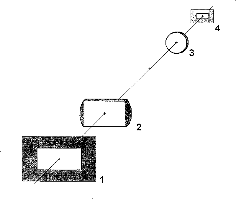
[0045] See first figure 1 , figure 1 It is a schematic diagram of the rectangular aperture telescope antenna of the synthetic aperture laser imaging radar of the present invention. figure 1 It is also a system schematic diagram of an embodiment of the present invention. It can be seen from the figure that the rectangular aperture telescope antenna of the synthetic aperture laser imaging radar of the present invention is composed of objective pupil 1, objective 2, eyepiece 3, and eyepiece pupil 4. The objective pupil 1 is located on the front focal plane of the objective lens 2. , The eyepiece pupil 4 is located on the back focal plane of the eyepiece 3, the objective lens 2 and the eyepiece 3 have rectangular apertures, and the focal length of the objective lens 2 is f 1 , The focal length of the eyepiece 3 is f 2 , The distance between the ...


PUM


Abstract

The invention relates to a rectangular aperture telescope antenna for a synthetic aperture laser imaging radar, which comprises an objective lens pupil, an objective lens, an eye lens and an eye lens pupil. The objective lens pupil is positioned on the front focal plane of the objective lens; the eye lens pupil is positioned on the back focal plane of the eye lens; the objective lens pupil, the objective lens, the eye lens and the eye lens pupil have rectangular apertures; the focus of the objective lens is f1; the focus of the eye lens is f2; and the distance between the objective lens and the eye lens is f1+f2. The invention can generate a rectangular optical toe according with the scanning mode of the synthetic aperture laser imaging radar, eliminate the phenomenon of uneven imaging resolution and reduced resolution of the optical toe in the azimuth direction and the vertical motion direction, and design optimal scale of the rectangular apertures to respectively control the scale of the laser radar optical toe in the azimuth direction and the vertical direction motion, so as to obtain large scanning width and high azimuth direction resolution.

Description

Technical field [0001] The invention relates to a synthetic aperture laser imaging radar, which is an optical telescope antenna with a rectangular aperture of a synthetic aperture laser imaging radar. It is used as an optical receiving and transmitting antenna and can produce a rectangular optical toe conforming to the scanning mode of the synthetic aperture laser imaging radar. It can not only eliminate the unevenness and decrease of the azimuth imaging resolution in the vertical direction of the optical toe movement, but also design the best rectangular aperture to control the lidar optical toe in the azimuth and the vertical direction. Scale, get large scan width and high azimuth resolution. Background technique [0002] The principle of synthetic aperture laser imaging radar is derived from the principle of synthetic aperture radar in the radio frequency field. It is the only optical imaging observation method that can obtain centimeter-level resolution at a long distance. H...

Claims


Application Information

Patent Timeline
Patent Type & Authority Patents(China)
IPC IPC(8): G01S7/481G01S17/89G02B23/00
Inventor 刘立人
Owner SHANGHAI INST OF OPTICS & FINE MECHANICS CHINESE ACAD OF SCI
Learn More