

Method and device for bus bar soft connection
A soft connection and bus joint technology, applied in the direction of busbar installation, cable installation, clamping/spring connection, etc., can solve the problems of unstable input power, unstable bus joint fixing, affecting production and life, etc. Reasonable design, the effect of solving poor contact between busbars and simple structure
Inactive Publication Date: 2009-06-24
梁波
View PDF0 Cites 19 Cited by
- Summary
- Abstract
- Description
- Claims
- Application Information
AI Technical Summary
Problems solved by technology
However, when used in an unfixed environment, such as when used on a wind turbine tower, its disadvantages will be exposed. Due to its environment, its busbar will naturally sway with the wind, resulting in loose fixation between busbar joints , the contact surface changes, the input power is unstable, and even the bus joint is broken, which affects normal production and life
Method used
View moreImage
Smart ImageViewing Examples

Examples
Embodiment 1
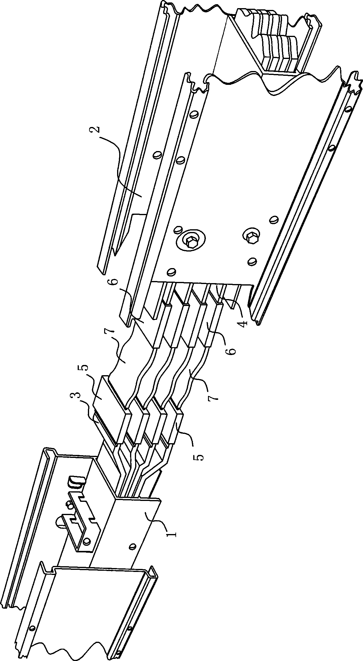
[0014] The method for flexible bus connection of the present invention is to connect the bus joint 3 of the bus duct 1 and the bus joint 4 of the bus duct 2 with a soft conductor material 7 .
Embodiment 2
[0016] The soft connection method of the busbars of the present invention is to fasten and connect the busbar joints 3 of the busway 1 and the busbar joints 4 of the busway 2 with the soft conductor material 7 .
Embodiment 3
[0018] The bus soft connection method of the present invention is that the bus joint 3 of the bus duct 1 and the bus joint 4 of the bus duct 2 are clamped with a soft conductor material 7, or tightly fitted or screwed.
Login to View More PUM
 Abstract
The invention relates to a bus soft connecting method; bus joints in a bus groove are connected by soft conductor materials; the soft conductor materials is connected with the bus joints in a checking way, or is spliced with the bus joints in a close matching way or is fixedly connected with a screw; plug sleeves are fixed at the two ends of the soft conductor materials and are spliced with the bus joints of the bus groove. The bus soft connecting method and the device thereof have reasonable design and simple structure, and can be used in a bus fixation occasion, and can be suitable for the environment of unfixed bus; the application range is wide, and the problem of poor contact among buses is solved; the joint fracture among buses or the change of the contact surfaces is effectively reduced and the normal operation in industrial production is ensured.
Description
technical field [0001] The invention belongs to a connection method and a device for a bus, in particular to a method and a device for a soft connection of a bus. Background technique [0002] The busbar is the conductor that connects the cut-off branch circuits in the electrical device together. It is the carrier for collecting and distributing power, also known as busbar. It is customary to refer to the conductors of the current-carrying branch circuits in each power distribution unit as bus bars. The function of the busbar is to collect, distribute and transmit electrical energy. Due to the above-mentioned functions of the busbar, a large number of busbars are used in power distribution projects in factories of industrial and mining enterprises, large buildings, ships and drilling platforms, and the length of each busbar is about 3 to 6 meters. Placed in the bus duct and connected in turn to achieve the purpose of power transmission. There are joints at both ends of t...
Claims
Login to View More Application Information
Patent Timeline
 IPC IPC(8): H02G5/00H01R4/28
Inventor梁波
Owner梁波