Image diagnosis support device and image diagnosis support program

An auxiliary device and image diagnosis technology, which is applied in the directions of diagnosis, image enhancement, image analysis, etc., and can solve the problem that it is difficult for doctors to find abnormal parts.

Active Publication Date: 2009-06-24
HITACHI HEALTHCARE MFG LTD
View PDF1 Cites 3 Cited by
  • Summary
  • Abstract
  • Description
  • Claims
  • Application Information

AI Technical Summary

Problems solved by technology

[0005] That is, the following unsolved problem remains in the conventional image diagnosis support device, that is, the abnormality is not conspicuous in all the tomographic images, and it is difficult for the doctor to measure only a part of the tomographic images. Abnormal parts found

Method used


Image

  • Image diagnosis support device and image diagnosis support program
  • Image diagnosis support device and image diagnosis support program
  • Image diagnosis support device and image diagnosis support program

Examples


no. 1 approach

[0037] refer to Figure 2 to Figure 7 The first embodiment will be described.

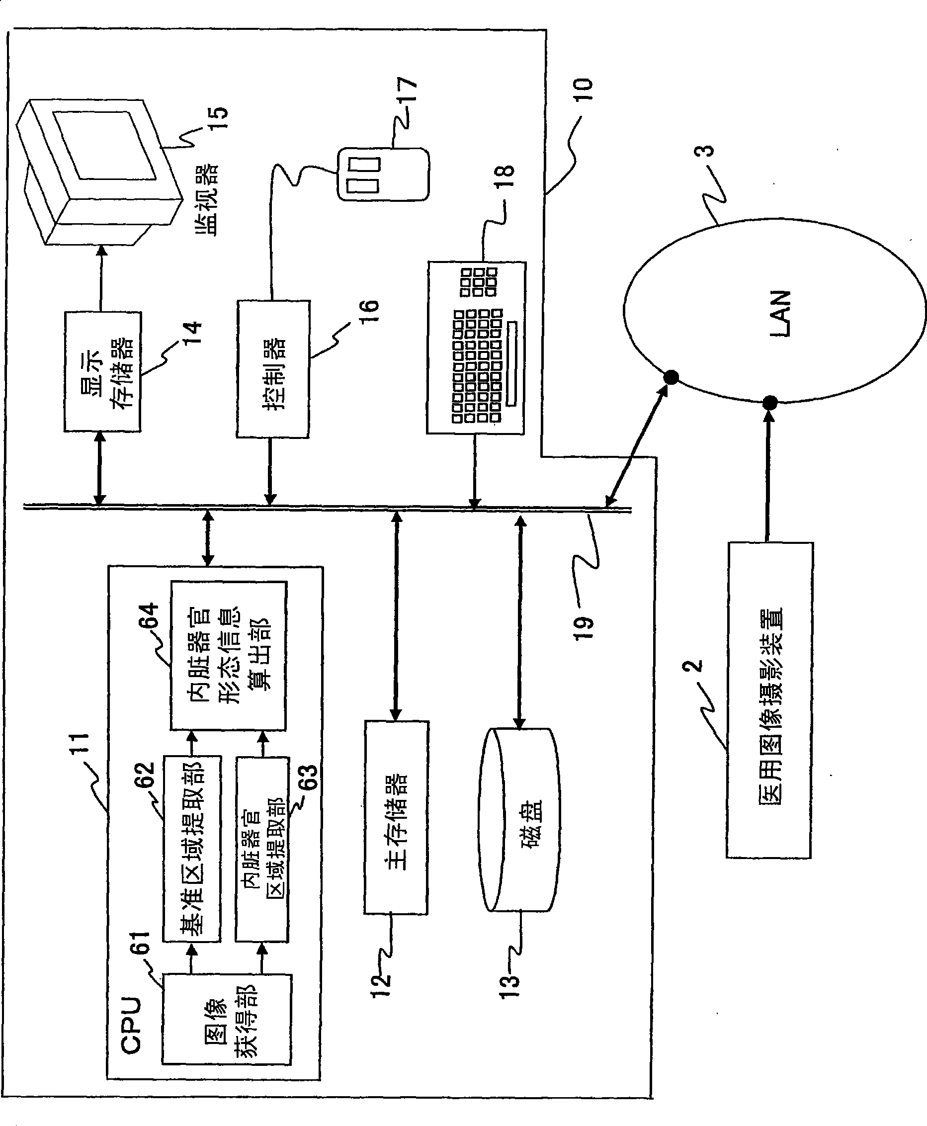
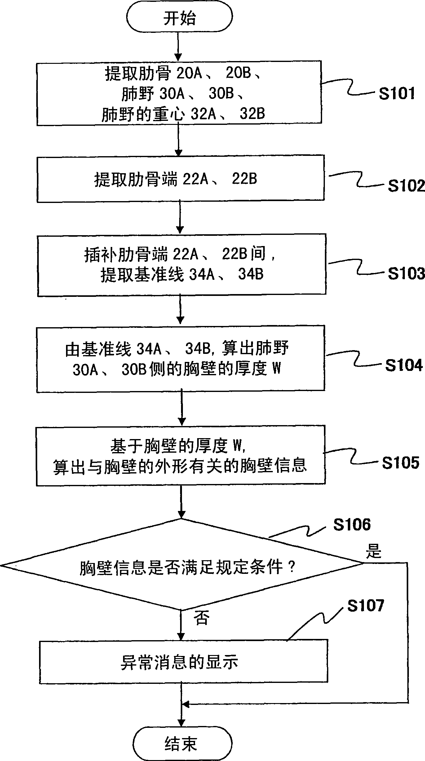
[0038] figure 2 It is a flowchart showing the processing of the image diagnosis support device.

[0039] The CPU 11 (image obtaining unit 61 ) obtains medical images (axial images, three-dimensional images, etc.) of the subject's lungs from the medical imaging device 2 or the magnetic disk 13 , and develops them in the main memory 12 .

[0040](step S101)

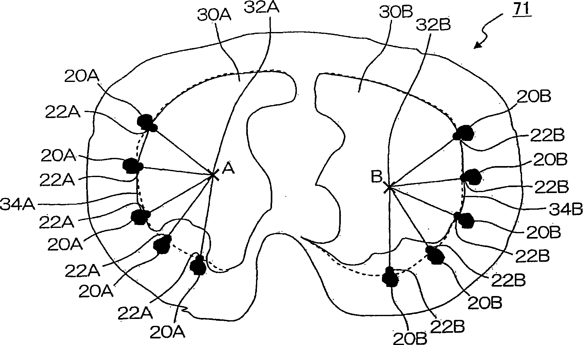
[0041] image 3 It is an explanatory diagram showing a reference line calculation method when calculating the thickness of the chest wall.

[0042] The CPU 11 (reference area extracting unit 62 ) performs threshold processing on the axial image 71 developed in the main memory 12 to extract the respective left and right ribs 20A and 20B. The CPU 11 (organ region extraction unit 63 ) performs threshold processing on the axial image 71 developed in the main memory 12 to extract the lung field 30A and the lung field 30B. In the threshold proc...

no. 2 approach

[0065] Second, refer to Figure 8 A second embodiment will be described.

[0066] Figure 8 It is an explanatory diagram showing a method of calculating the thickness of the chest wall according to the second embodiment.

[0067] The processing from step S101 to step S103 and step S105 to step S107 is the same as that in the first embodiment, and therefore description thereof will be omitted.

[0068] In step S104, the following process is performed to calculate the thickness W of the chest wall on the side of the lung field 30A and the lung field 30B using the reference line 34A and the reference line 34B. The CPU 11 (organ region extracting unit 63 ) calculates the region surrounded by the reference line 34A and the reference line 34B, and the line 44A and the line 44B parallelly moving the reference line 34A and the reference line 34B toward the lung field 30A and the lung field 30B by a distance t. 42A and area 42B. That is, the region 42A and the region 42B are passin...

no. 3 approach

[0071] Second, refer to Figure 9 A third embodiment will be described.

[0072] Figure 9 It is an explanatory diagram showing a method of calculating the thickness of the chest wall according to the third embodiment.

[0073] The processing from step S101 to step S103 and step S105 to step S107 is the same as that of the first embodiment, and thus description thereof will be omitted.

[0074] In step S104, the following process is performed to calculate the thickness W of the chest wall on the side of the lung field 30A and the lung field 30B from the reference line 34A and the reference line 34B. The CPU 11 (organ region extraction unit 63 ) passes through the lung field 30A and the lung field 30B along the normal line of the reference line 34A and the reference line 34B at the points 36A and 36B on the back side of the reference line 34A and the reference line 34B. The straight line 48A and the straight line 48B having the length 1 are subjected to threshold value proce...


PUM


Abstract

An image diagnosis support device 10 of the present invention includes an image acquisition section 61 which acquires a tomographic image including a desired organ of an object from a medical image scanning apparatus 2 or a magnetic disk 13; a reference region extraction section 62 which extracts a reference region representing a reference in the organ of interest from the tomographic image acquired by the image acquisition section 61; an organ region extraction section 63 which extracts an organ region representing a region of the organ of interest from the tomographic image acquired by the image acquisition section 61; an organ shape information calculation section 64 which calculates organ shape information regarding the shape of the organ of interest from the reference region extracted by the reference region extraction section 62 and the organ region extracted by the organ region extraction section 63; and display control means 11 which displays on a monitor 15, which is a display device, the organ shape information calculated by the organ shape information calculation section 64.

Description

technical field [0001] The present invention relates to an image diagnosis support device, and more particularly, to an image diagnosis support device and an image diagnosis support program for detecting the deformed state of a specific internal organ such as a thickened chest wall. Background technique [0002] Conventionally, in an image diagnosis support device, an operator specifies a point or an area on a medical image with a finger to measure a distance or an area (for example, refer to [Patent Document 1]). [0003] Patent Document 1: Japanese Patent Laid-Open No. 2005-65845 [0004] In recent years, diseases caused by asbestos inhalation have become a social problem. People who inhale large amounts of asbestos have a tendency to thicken the chest wall. Abnormalities in the thickness of the chest wall are detected visually by a physician, but abnormalities may be overlooked in a visual inspection. [0005] That is, the following unsolved problem remains in the conv...

Claims


Application Information

Patent Timeline
Patent Type & Authority Applications(China)
IPC IPC(8): A61B6/03
CPCG06T2207/10072G06T7/0012A61B5/1075A61B6/032A61B5/055A61B6/463G06T2207/30061
Inventor 后藤良洋
Owner HITACHI HEALTHCARE MFG LTD
Why Eureka
Try Eureka