Reference image display method for ultrasonography and ultrasonograph

A technology of reference image and ultrasonic image, applied in ultrasonic/sonic/infrasonic diagnosis, sonic diagnosis, infrasonic diagnosis, etc., can solve problems such as operator burden

Active Publication Date: 2006-07-19
HITACHI HEALTHCARE MFG LTD
View PDF2 Cites 23 Cited by
  • Summary
  • Abstract
  • Description
  • Claims
  • Application Information

AI Technical Summary

Problems solved by technology

[0003] However, when CT images or MR images are only used as reference images, it is a great burden on the operator to identify the correlation between images

Method used


Image

  • Reference image display method for ultrasonography and ultrasonograph
  • Reference image display method for ultrasonography and ultrasonograph
  • Reference image display method for ultrasonography and ultrasonograph

Examples


no. 1 example

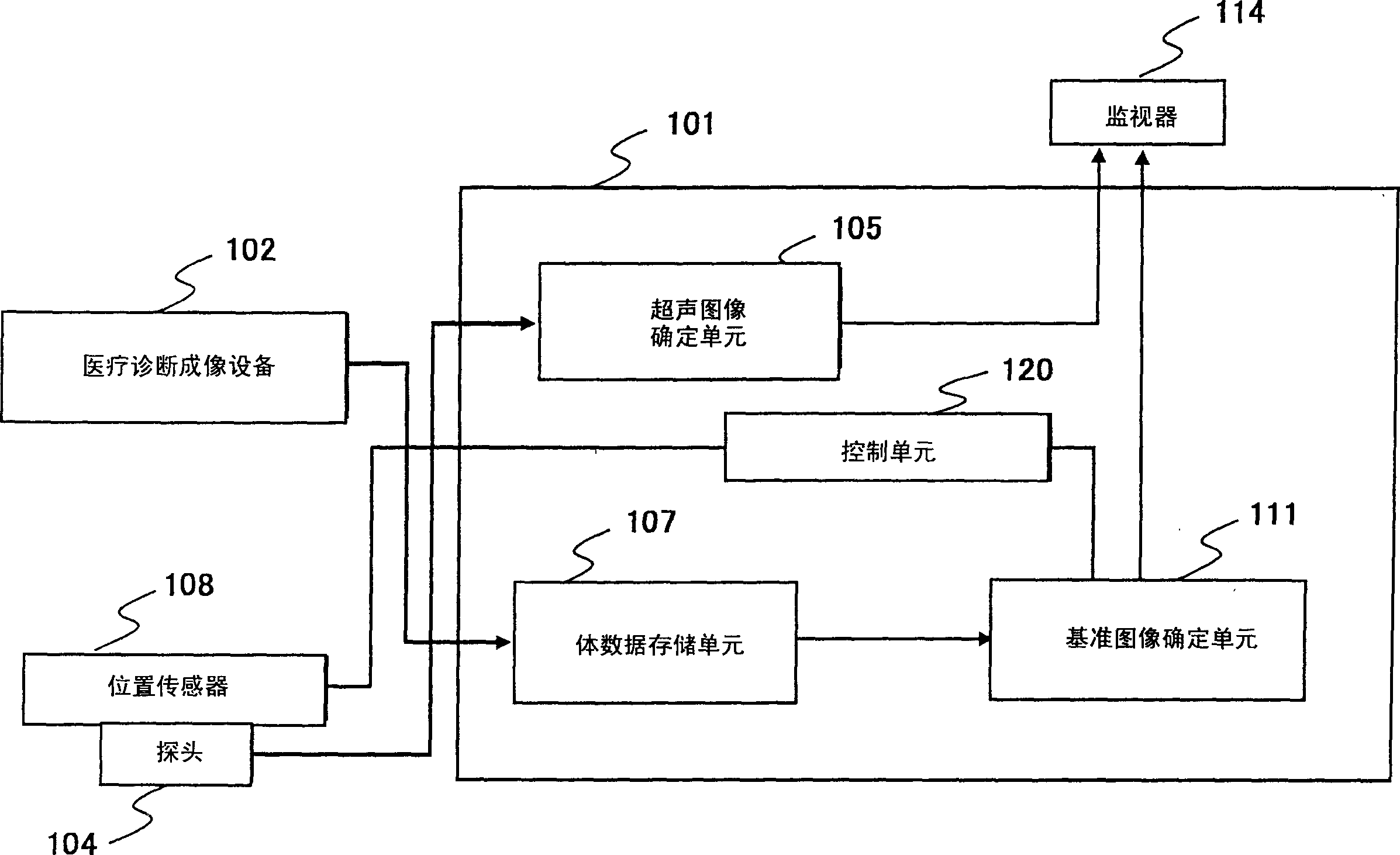
[0039] figure 1 is a block diagram of a basic ultrasonic imaging system to which an ultrasonic diagnostic apparatus of one embodiment of the present invention is applied. As shown in the figure, the diagnostic imaging system includes an ultrasonic diagnostic apparatus 101 according to an embodiment of the present invention and a medical diagnostic imaging apparatus 102 for obtaining volumetric image data as a reference image. Volume image data refers to data of a multi-slice image obtained by capturing the inside of a patient's body along a plurality of planes. Data of volume images captured by the medical diagnostic imaging device 102 are input to the ultrasonic diagnostic device 101 . A computed tomography device (X-ray CT device) or a magnetic resonance imaging device (MRI device) may be used as the medical diagnostic imaging device 102 . It is well known that CT images and MR images have better image quality than ultrasound images and are therefore suitable as reference ...

no. 2 example

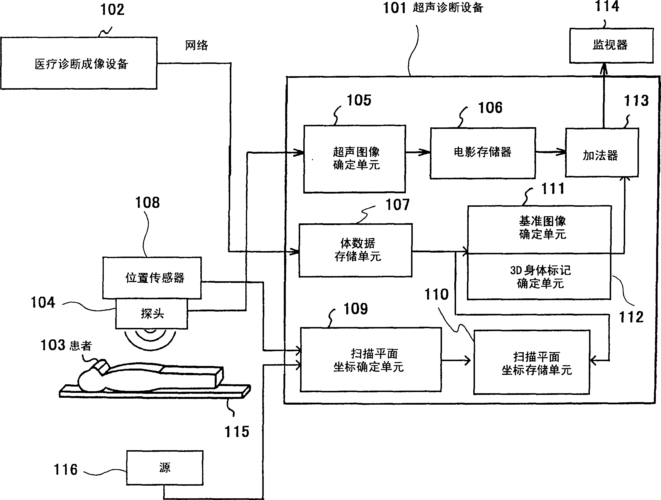
[0045] figure 2 is a block diagram of a special diagnostic imaging system to which the ultrasonic diagnostic apparatus of the present invention is applied. exist figure 2 , use the same reference numerals to denote figure 1 devices with the same functional configuration, and descriptions thereof are omitted. exist figure 2 Among them, the scanning plane coordinate determination unit 109 and the scanning plane coordinate storage unit 110 correspond to the configuration of the main units of the control unit 120 . The cine memory 106 stores the ultrasound image reconstructed by the ultrasound image determination unit 105 . The 3D body marker determination unit 112 is configured to be connected to the reference image determination unit 111 . The adder 113 is configured as image processing means for appropriately combining the images generated by the cine memory 106 , the reference image determination unit 111 and the 3D body marker determination unit 112 . The monitor 114...

no. 3 example

[0064] Image 6 The configuration of a diagnostic imaging system to which an ultrasonic diagnostic apparatus of another embodiment of the present invention is applied is shown. exist Image 6 in, with figure 2 The illustrated embodiment is different in that a respiration sensor 117 for detecting the breathing amount of the patient 103 and a posture sensor 118 for detecting body movement are provided, and the detected output is input to the scan plane coordinate determination unit 109 . Although in figure 2 In the embodiment of the present invention, the processing of correlating the coordinate system of the volume image data with the coordinate system of the scanning plane is omitted, and the processing will be described in detail below.

[0065] In this example, if Figure 7A As shown, a position sensor 108 is attached to one surface of the probe 104 so that it is possible to detect the position and inclination of the probe 104 , ie the position and inclination of the u...


PUM


Abstract

Ultrasonograms (105, 106) are created by means of ultrasonic probe (104). Volume image data is created previously by using an image diagnosis apparatus (102) and stored in a volume data storage unit (107). From the stored volume image data, a tomogram corresponding to the scan surface of the ultrasonic images is extracted, and a reference image (111) is formed from the tomogram. The ultrasonograms and the reference image are displayed on the same screen (114). An area of the reference image corresponding to the viewing area of the ultrasonogram is extracted, and a reference image of the same portion as that of the ultrasonic image is displayed as a fan image and/or displayed with the same magnification as that of the ultrasonograms.

Description

technical field [0001] The present invention relates to a reference image display method for ultrasonic imaging and ultrasonic diagnostic equipment using the method. More specifically, the present invention relates to a technique preferably for real-time reconstruction using multislice image data of a patient obtained by diagnostic imaging equipment, a reference image of the same cross-section as the ultrasound scan plane, and for real-time reconstruction at the same The reference image and the ultrasound image are displayed on the screen. Examples of such diagnostic imaging equipment include ultrasonic diagnostic equipment, magnetic resonance imaging (MRI) equipment, and X-ray computed tomography (X-ray CT) equipment. Background technique [0002] Ultrasonic diagnostic equipment as a diagnostic imaging device is commonly used for diagnosis because they are easy to operate and can perform noninvasive observation of arbitrary cross-sections in real time. On the other hand, ...

Claims


Application Information

Patent Timeline
Patent Type & Authority Applications(China)
IPC IPC(8): A61B8/00G06T19/00
Inventor 荒井修岩崎隆雄三竹毅押尾晃一大熊洁新本弘
Owner HITACHI HEALTHCARE MFG LTD
Why Eureka
Try Eureka