Inflating device for gas packaging bag

An inflatable device and packaging bag technology, applied in the direction of pressurized/gasified packaging, etc., can solve the problem of reducing work efficiency and achieve the effect of improving work efficiency

Inactive Publication Date: 2011-11-30
BOMPAK INT
View PDF0 Cites 0 Cited by
  • Summary
  • Abstract
  • Description
  • Claims
  • Application Information

AI Technical Summary

Problems solved by technology

But when the operator held and controlled the air gun 100 with the right hand, the left hand must hold the film at the air inlet 220 of the air bag that is inserted into the air nozzle of the air gun 100 to prevent the air nozzle of the air gun 100 from contacting the gas bag. The air inlet 220 is separated, which affects the charging process
Moreover, the posture of holding the left and right hands at the same time must continue until the end of the entire inflation operation, thus limiting the possibility of the operator's hands being engaged in other operations, and greatly reducing work efficiency.

Method used


Image

  • Inflating device for gas packaging bag
  • Inflating device for gas packaging bag
  • Inflating device for gas packaging bag

Examples


Embodiment 1

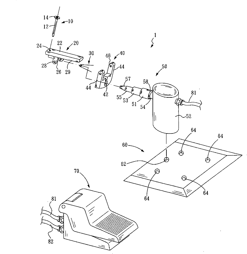
[0022] Example 1, an inflation device for gas packaging bags, please refer to figure 2 , Is a three-dimensional exploded schematic diagram of the inflator 1. The inflator 1 includes: a buckle member 10, a control member 20, a control spring 30, a shaft base 40, a support base 50, a fixed base 60, and a control pedal 70. The buckle member 10 has a round rod 12, and a round disk 14 is screwed on the top of the round rod 12, and the diameter of the round disk 14 is much larger than the round rod 12. The manipulating member 20 has a plate 22, and the left end of the plate 22 is provided with a perforation 24. The diameter of the perforation 24 is the same as the diameter of the rod 12 of the buckling member 10, which is just for the rod 12 to pass through. A pair of ear seats 26 are provided on both sides of the bottom of a third part of the plate 22 near the perforation 24, and the bottom end of the ear seats 26 is provided with a shaft hole 28. In addition, the bottom of the pl...

Embodiment 2

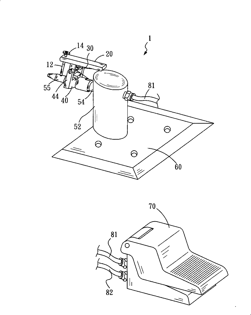
[0025] Example 2, please refer to Figure 5 , Is a three-dimensional exploded schematic diagram of Embodiment 2 of the present invention. The inflator 1 includes: a buckle member 10, a control member 20, a control spring 30, a shaft base 40, a support base 50, a fixing base 60, a control pedal 70, and a clamping member 90. The buckling member 10, the control member 20, the control spring 30, the shaft base 40, the support seat 50, the fixing seat 60, and the control pedal 70 are substantially the same as those of the aforementioned embodiment 1. The main difference is that the buckle member 10 The round rod 12 is shorter, and a round hole 16 is provided at the bottom end of the round rod 12. In addition, a clamping member 90 is provided. The clamping member 90 has left and right clamping seats 91, 92, each of the left and right clamping seats 91, 92 forms a semicircular curve. The diameter of the small rod 55 of the air outlet member 54 of the seat 50 is the same. The top si...


PUM


Abstract

Inflating device for gas packaging bags: the round rod of the crimping part passes through the perforation of the control part, and the crimping part and the control part are placed above the shaft base, and a shaft is inserted through the shaft hole of the cantilever, the shaft hole of the lug seat, Control the spring coil of the spring, and then pass through the shaft hole of the trunnion and the shaft hole of the cantilever in sequence, erect the control part and the buckle part on the cantilever of the shaft frame to form a swing part; Pass the air outlet of the support seat and position it at the middle rod of the air outlet; one foot of the two extension legs of the control spring is buckled on the spring placement part of the plate, and the other foot is buckled on the buckle platform of the air outlet, and the buckle is pressed The front end of the round rod of the air outlet part touches the small rod of the air outlet part; the cylinder seat lock screw of the support seat is fixed on the fixed seat, and one end of the air outlet pipe is connected to the control pedal, and the other end is connected to the cylinder seat; one end of the air intake pipe Connect to the control pedal, and the other end to the air intake source. The invention can facilitate the inflation operation and significantly improves the work efficiency.

Description

Technical field [0001] The invention relates to an inflator for a gas packaging bag. The inflator includes a buckle member, a control member, a control spring, a shaft base, a support base, a fixed base, and a control pedal. Background technique [0002] The prior art gas packaging bag inflation method, such as figure 1 As shown, the gas nozzle of an inflation gun 100 penetrates into the air inlet 220 of the gas packaging bag 200, and then the gas inlet switch 120 of the inflation gun 100 is pressed to inflate the gas packaging bag 200 so that the gas flows along The air inlet 240 enters each independent air chamber 210. However, when the operator holds the control inflation gun 100 with the right hand, the left hand must hold the film at the air inlet 220 of the gas packaging bag that is inserted into the gas nozzle of the inflation gun 100 to prevent the gas nozzle and the gas packaging bag of the inflation gun 100 The air inlet 220 is separated, which affects the progress of ...

Claims


Application Information

Patent Timeline
Patent Type & Authority Patents(China)
IPC IPC(8): B65B31/04
Inventor 陈政涌
Owner BOMPAK INT
Why Eureka
Try Eureka