Mounting method for underbeam segment of large-stride steel box girder stayed-cable bridge

A technology for cable-stayed bridge towers and installation methods, which is applied to bridges, bridge construction, erection/assembly of bridges, etc., can solve the problems of impractical implementation and high construction costs, and achieve small construction conditions, economical convenience, and simple and practical installation methods Effect

Active Publication Date: 2010-10-27
SICHUAN ROAD & BRIDGE GRP
View PDF4 Cites 0 Cited by
  • Summary
  • Abstract
  • Description
  • Claims
  • Application Information

AI Technical Summary

Problems solved by technology

Using this method to install the lower beam section of the tower not only has a high construction cost, but also is restricted by the conditions of the construction site: because large-scale floating cranes generally have a relatively large travel depth, it is required that the water near the tower foundation must have sufficient water depth. Otherwise the method is completely impractical

Method used


Image

  • Mounting method for underbeam segment of large-stride steel box girder stayed-cable bridge
  • Mounting method for underbeam segment of large-stride steel box girder stayed-cable bridge
  • Mounting method for underbeam segment of large-stride steel box girder stayed-cable bridge

Examples


Embodiment 1

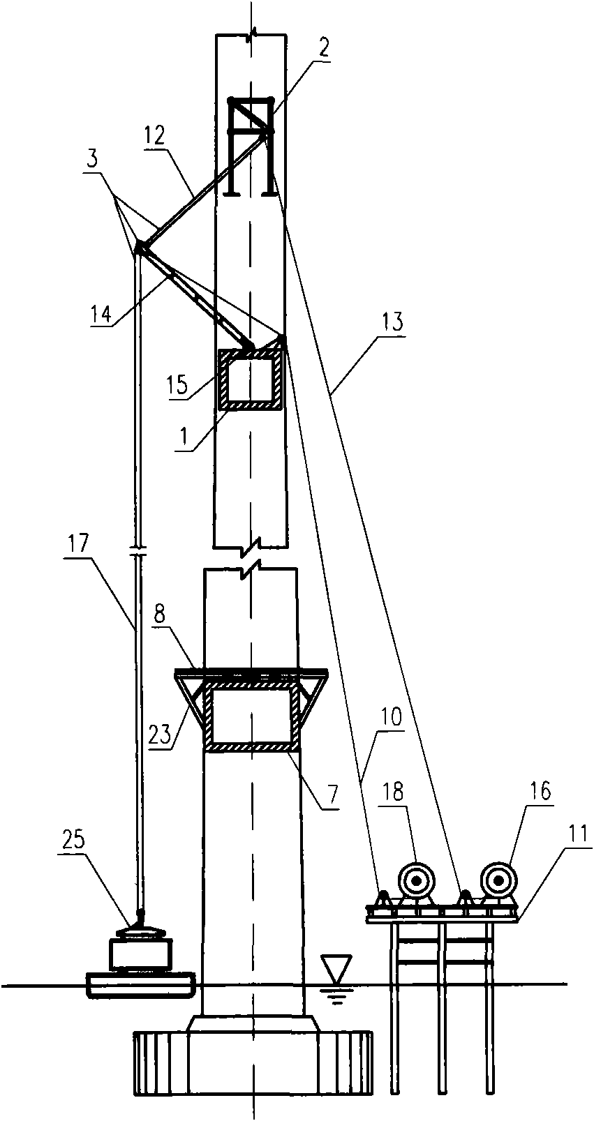
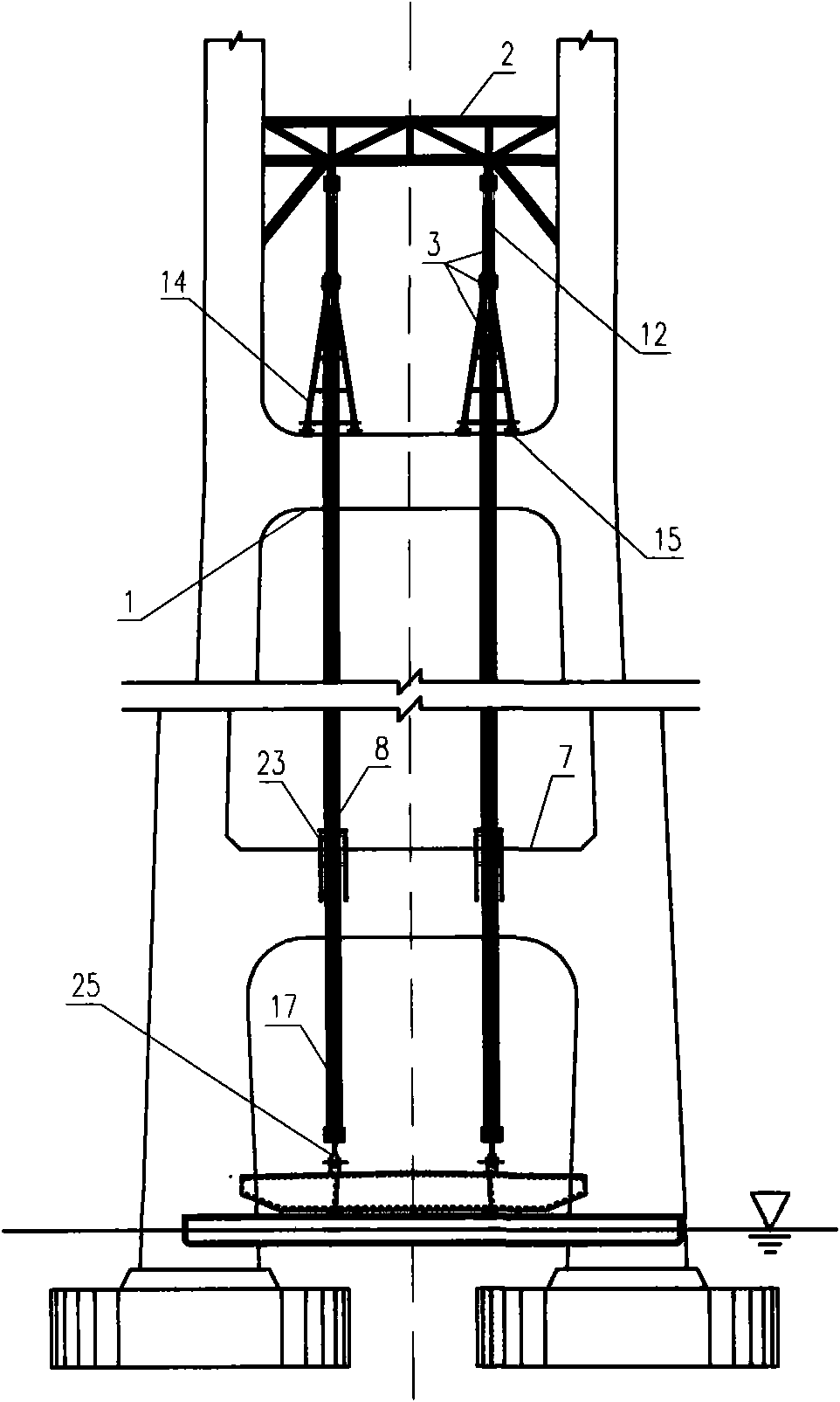
[0039] like Figure 1-12 Shown, the construction steps of the installation method of the tower lower girder section of the long-span steel box girder cable-stayed bridge of the present invention are:

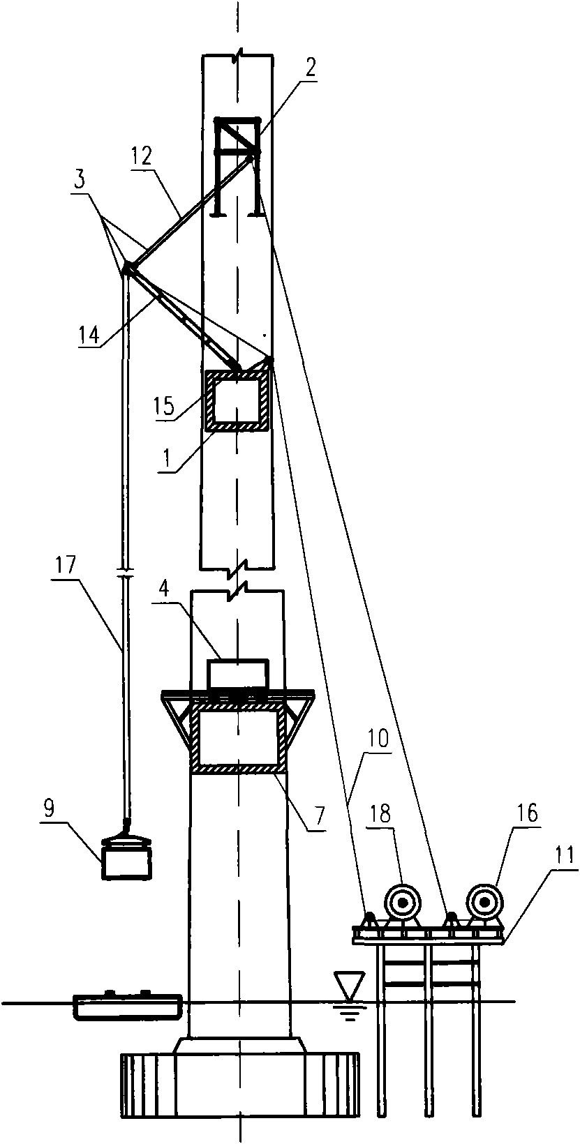
[0040] (1) set up the mast type crane 3 and lift the steel box girder 4, 9, 24 in the tower area by means of the construction wind mechanism 2 used during the cable tower upper beam 1 and cable tower construction,

[0041] (2) Install deck cranes 5 and 19 on the steel box girders 4, 9 and 24 in the tower area to lift the first standard beam sections 6 and 20 adjacent to the steel box girders 4 and 24 in the tower area,

[0042] (3) Install the deck cranes 5 and 19 symmetrically on the installed first section standard beam sections 6 and 20, and start the symmetrical hoisting of the standard beam sections 21 and 22 on the river center side and shore side.

[0043] The construction steps of the installation method of the lower girder section of the above-mentioned long-span steel...

Embodiment 2

[0058] Except: E. Lift the first standard beam section 20 of the shore side with the bridge deck crane 5 installed in place, install it in place and complete the hanging cable; G. Lift the first standard beam section 20 of the river center side and place it Complete hanging rope, H, bridge deck crane 5 walks on the first joint standard beam section 6 of the river center side, I, bridge deck crane 19 is installed on the bank side first joint standard beam section 20, start the river center side Except for the symmetrical hoisting construction of the standard beam sections 21 and 22 on the shore, the rest are the same as in Embodiment 1.

Embodiment 3

[0060] Except: mast 14 is the steel mast that is installed on the cable tower upper beam 1, all the other are identical with embodiment 1.


PUM


Abstract

The invention relates to a large span steel box girder cable-stayed bridge tower lower beam segment mounting method, belonging to the bridge construction steel box girder construction technology field. The construction method comprises the steps: (1) setting up a masts type crane lifting tower area steel box girder by means of the upper crossbeam of the cable tower and the construction wind; (2) mounting the bridge deck crane in on the tower area steel box girder and lifting the first standard beam segment immediately adjacent to the tower area steel box girder; (3) mounting the bridge deck crane symmetrically on the mounted first standard beam segment, and starting the standard beam segment symmetrical hanging on both the river side and the bank side. The method in the invention achievesthe advantages of simple, practical, safe, reliable, economic, convenient less limited by the construction condition, solves the problems in present large span steel box girder cable-stayed bridge construction process.

Description

Technical field: [0001] The invention belongs to the technical field of steel box girder construction for bridge construction, and in particular relates to a method for installing a lower girder section of a steel box girder cable-stayed bridge tower with a large span. Background technique: [0002] With the continuous development of bridge design and construction technology, more and more long-span steel box girder cable-stayed bridges are being built. However, there are still many unsolved problems in the construction of long-span steel box girder cable-stayed bridges. For example, the problem of how to safely, economically and quickly complete the construction of the lower girder section of the long-span steel box girder cable-stayed bridge has not been well resolved. In the past, the installation methods of the lower girder section of the long-span steel box girder cable-stayed bridge include: the frame crane method and the frame floating method, but both methods have o...

Claims


Application Information

Patent Timeline
Patent Type & Authority Patents(China)
IPC IPC(8): E01D21/00
Inventor 于志兵聂东张佐安裴宾嘉甘洪罗明勇姚德波申传贵
Owner SICHUAN ROAD & BRIDGE GRP
Why Eureka
Try Eureka