
Magnetic positioning method and device in high background magnetic field

A technology of background magnetic field and magnetic positioning, which is applied in the field of magnetic positioning, can solve the problems of being unable to apply to the high background magnetic field environment with changes in size and direction, and achieve the effect of reliable positioning and real-time positioning

Inactive Publication Date: 2009-07-08
INST OF ELECTRICAL ENG CHINESE ACAD OF SCI
View PDF4 Cites 35 Cited by
  • Summary
  • Abstract
  • Description
  • Claims
  • Application Information

AI Technical Summary

Problems solved by technology

[0006] The purpose of the present invention is to overcome the shortcomings of the prior art that cannot be applied to the high background magnetic field environment with changes in size and direction, and propose a method and device for tracking a target object under a high background magnetic field

Method used


Image

  • Magnetic positioning method and device in high background magnetic field
  • Magnetic positioning method and device in high background magnetic field
  • Magnetic positioning method and device in high background magnetic field

Examples


Embodiment Construction

[0038] The present invention will be further described below in conjunction with the accompanying drawings and specific embodiments.

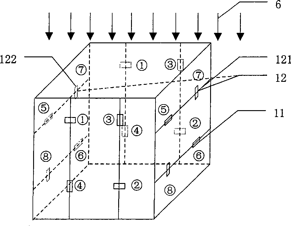
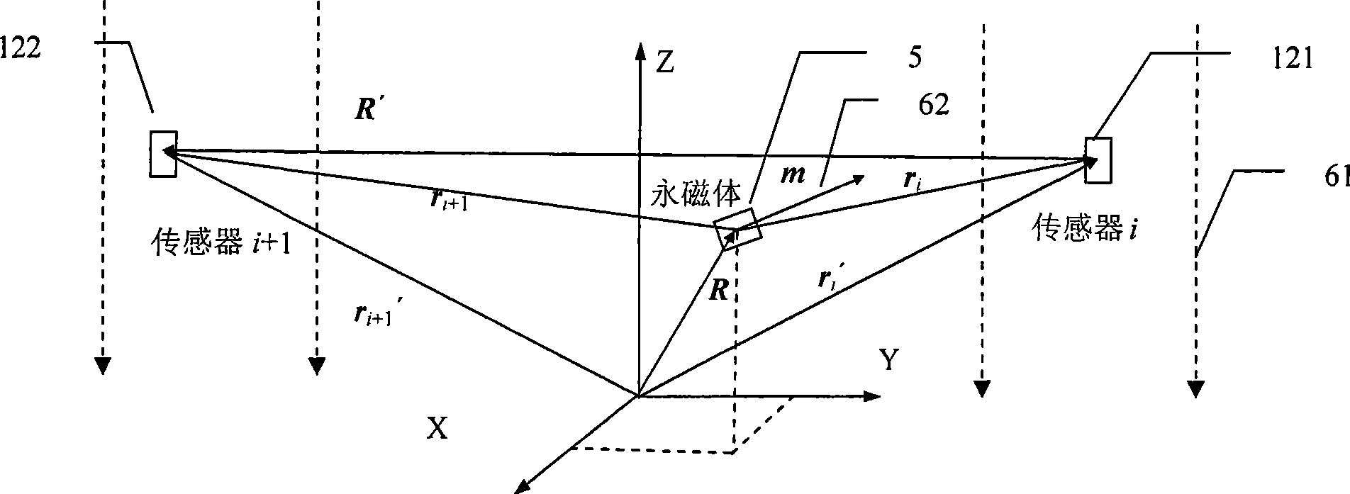
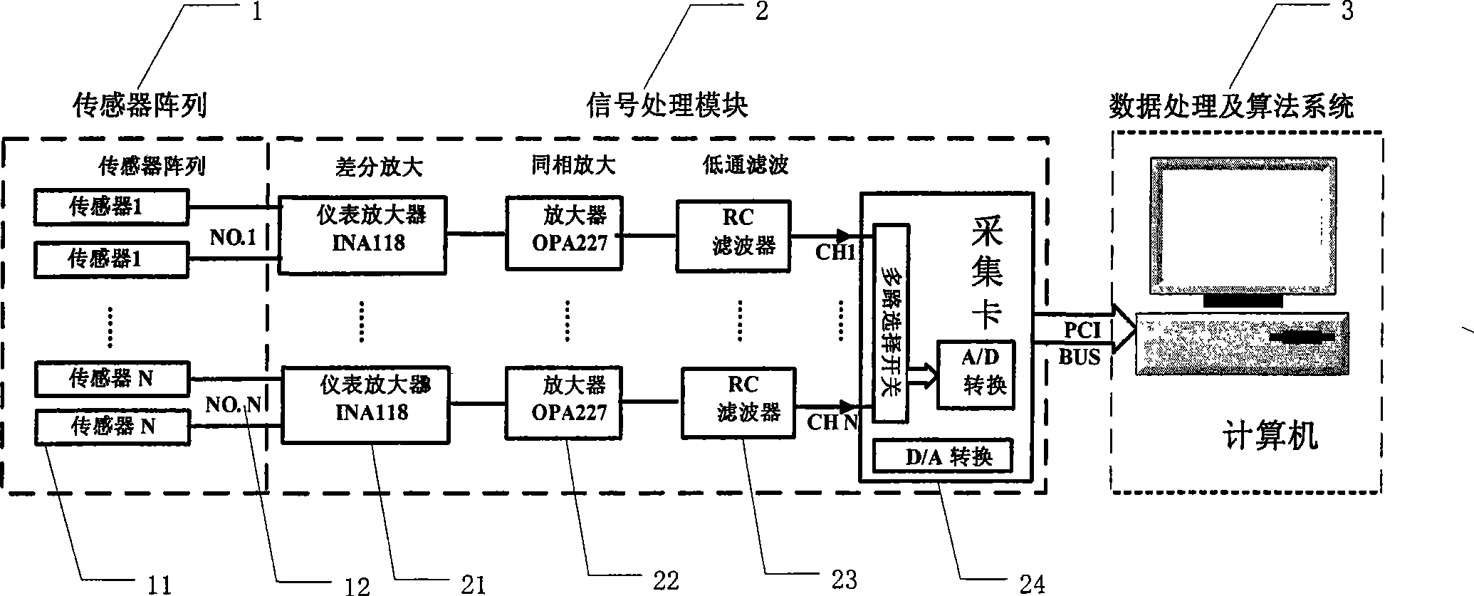
[0039] The present invention is used for magnetic localization of target objects under a high background magnetic field 61 of varying magnitude and direction. A permanent magnet block 5 is fixed inside the target object. The present invention includes sensor array 1, signal processing module 2 and data processing and algorithm system 3, such as image 3 shown.

[0040] The sensors in the sensor array 1 adopt GMR or Hall uniaxial sensors to measure the background magnetic field in the sensitive axis direction of each sensor and the magnetic induction intensity of the permanent magnet block of the target object, such as image 3 shown. The sensor array 1 is composed of N sets of sensor groups, where N≥5. Each sensor group is composed of two sensors, the number of sensor groups is greater than or equal to 5 groups, and the total number of sens...


PUM


Abstract

The invention relates to a magnetic positioning method in high background magnetic fields, which comprises: using a sensor group which is arranged on two spatially symmetrical position points to detect background magnetic fields and magnetic fields of a permanent magnetic block of a target object, adopting a differential amplifier circuit to take equal magnetic induction intensity of the background fields detected by the sensor group as common-mode signals for subtraction, eliminating the high background magnetic fields, and obtaining a magnetic induction intensity difference value of the permanent magnetic block of the target object on the two sensor position points in the sensor group; using N (N is more than or equal to 5) groups of sensor groups for measurement, and obtaining a magnetic induction intensity difference value vector which comprises N (N is more than or equal to 5) magnetic induction intensity difference values; adopting a differential magnetic positioning algorithm to obtain a differential magnetic positioning equation system; establishing an objective function by the differential magnetic positioning equation system and the magnetic induction intensity difference value vector which is obtained by actual measurement; and solving the objective function, and obtaining the three-dimensional position and the two-dimensional attitude of the permanent magnetic block of the target object. A device applying the positioning method comprises a sensor array (1), a signal processing module (2) and a data processing and algorithm system (3).

Description

technical field [0001] The invention relates to a magnetic positioning method and device under a high background magnetic field, in particular to a magnetic positioning method and device for a target object when the size and direction of the background magnetic field change. Background technique [0002] According to a specific distribution of the magnetic field, the method of calculating the position or attitude of the target object is the magnetic positioning method. With the development of modern industrial technology, there are more and more applications where the magnetic field distribution is used to locate the target object. The magnetic positioning method can not only be applied in navigation and surgical navigation, but also can complete the positioning of buoys and underwater devices, drilling positioning, aviation positioning, integration with GPS for vehicle navigation and other aspects. [0003] Generally speaking, there are two types of magnetic positioning me...

Claims


Application Information

Patent Timeline
IPC IPC(8): G01B7/00
Inventor 宋涛王喆王金光杨芩玉王明
Owner INST OF ELECTRICAL ENG CHINESE ACAD OF SCI
Learn More