Eureka AIR delivers breakthrough ideas for toughest innovation challenges, trusted by R&D personnel around the world.

Short-loop optical fiber gyroscope

A fiber optic gyroscope, short loop technology

Inactive Publication Date: 2009-07-08
ZHEJIANG UNIV
View PDF0 Cites 13 Cited by
  • Summary
  • Abstract
  • Description
  • Claims
  • Application Information

AI Technical Summary

Problems solved by technology

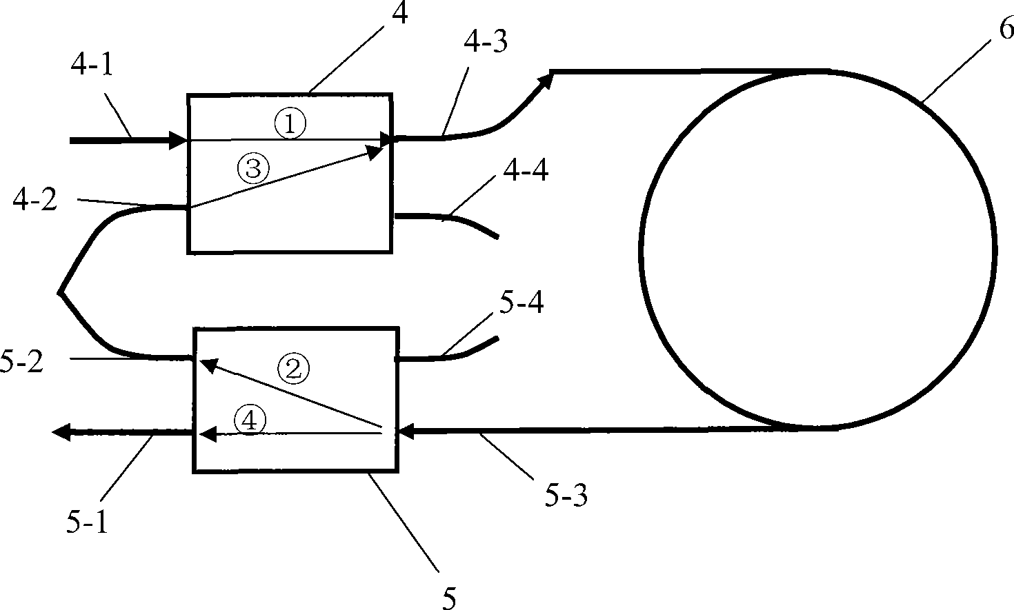
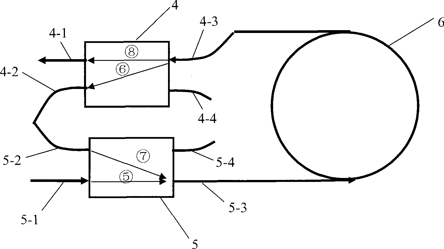
[0003] The purpose of the present invention is to provide a short-ring fiber optic gyroscope for the deficiencies of the prior art, which effectively solves the problems of complex fabrication and environmental sensitivity of conventional high-precision fiber optic gyroscopes

Method used


Image

  • Short-loop optical fiber gyroscope
  • Short-loop optical fiber gyroscope
  • Short-loop optical fiber gyroscope

Examples


Embodiment Construction

[0012] Such as figure 1 As shown, a short-ring fiber optic gyroscope includes a broadband light source 1 , a first coupler 2 , a Y waveguide 3 , a second coupler 4 , a third coupler 5 , an optical fiber ring 6 , and a detector 7 .

[0013] The wide-spectrum light source 1 is connected to the input port 2-1 at one end of the first coupler 2, the detector 7 is connected to the output port 2-2 at one end of the first coupler 2, and a port 2-3 at the other end of the first coupler 2 Connect to the single-ended port of Y-waveguide 3. One port in the double-ended port of the Y waveguide 3 is connected with a port 4-1 at one end of the second coupler 4, and another port in the double-ended port of the Y waveguide 3 is connected with a port 5-1 at one end of the third coupler 5. 1 connection, and another port 4-2 at one end of the second coupler 4 is connected with another port 5-2 at one end of the third coupler 5. A port 4-3 at the other end of the second coupler 4 is connected wi...


PUM


Abstract

The invention relates to a short-loop fiber optic gyroscope. The prior method for improving the precision of the fiber optic gyroscope by increasing the length of a fiber optic ring leads to the great limitation of the dynamic range of the gyroscope and the reduction in bandwidth. According to the method, an input port at one end of a first coupler is connected with a broadband light source, an output port of the first coupler is connected with a detector, and a port at the other end of the first coupler is connected with a single-end port of a Y waveguide. One port of double-end ports of the Y waveguide is connected with a port at one end of a second coupler, the other port of the double-end ports of the Y waveguide is connected with a port at one end of a third coupler, and the other port at the end of the second coupler is connected with the other port at the end of the third coupler. Two ends of the fiber optic ring are connected with a port at the other end of the second coupler and a port at the other end of the third coupler respectively. The gyroscope has larger dynamic range and bandwidth, reduces poor reciprocity caused by a winding defect of the fiber optic ring and improves the adaptability of the gyroscope.

Description

technical field [0001] The invention relates to an optical fiber gyroscope, in particular to a design of a short-ring optical fiber gyroscope with medium and low-precision optical fiber ring length of several hundred meters and a special optical system to achieve medium and high-precision indicators, and belongs to the technical field of optical fiber sensing. technical background [0002] As the key angle sensor of the new generation inertial navigation system, the fiber optic gyroscope has attracted much attention and developed rapidly because of its unparalleled anti-shock, anti-interference, high precision, and large dynamics. Its application range is more and more extensive, and its precision is getting higher and higher. The conventional way to increase the accuracy of the fiber optic gyroscope is to increase the length of the fiber optic ring. With the increase of the ring length, the dynamic range of the gyroscope is greatly limited, and the bandwidth is also reduced...

Claims


Application Information

Patent Timeline
Patent Type & Authority Applications(China)
IPC IPC(8): G01C19/72
Inventor 王冬云佘玄苏晓武刘承
Owner ZHEJIANG UNIV
Why Eureka
Eureka Blog
Learn More