Piston type or buoy type pressure meter effective area measuring method
A technology of effective area and measurement method, applied in the direction of measuring fluid pressure, measuring devices, instruments, etc., to achieve the effect of high practical significance and objective measurement results
- Summary
- Abstract
- Description
- Claims
- Application Information
AI Technical Summary
Problems solved by technology
Method used
Image

Examples
Embodiment 1
[0065] Embodiment 1 (basic application)
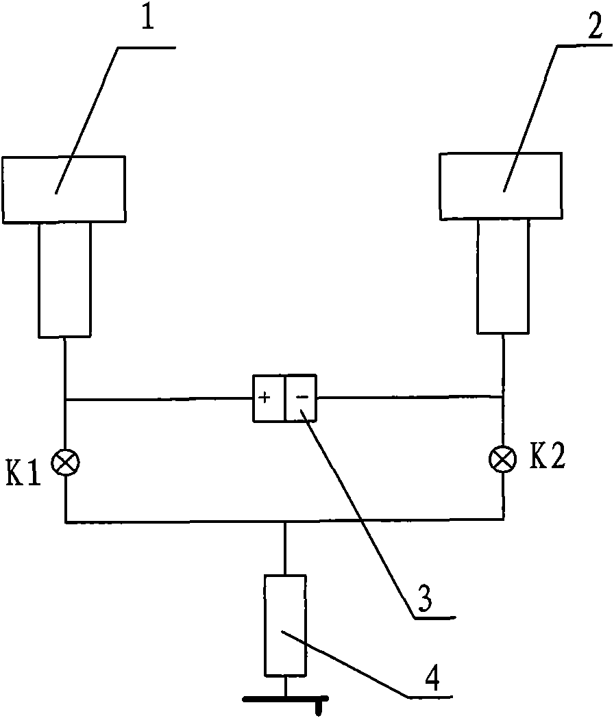
[0066] A pressure gauge effective area measuring device, such as figure 1 As shown, it is applied to the determination of the effective area of a piston pressure gauge, including a standard piston 1, a tested piston 2, a pressure source 4, and a differential pressure measurement device 3. The differential pressure measurement device 3 is a differential pressure transmitter 3, where the standard The piston 1 is connected to the positive pressure end of the differential pressure transmitter 3 and connected to the pressure source 4 through the first valve K1; the tested piston 2 is connected to the negative pressure end of the differential pressure transmitter 3 and passed through the second valve K2 Connect to pressure source 4.
[0067] 1) First select the differential pressure transmitter, taking the effective area of a 0.05-level (second-class) piston pressure gauge measuring 0.25MPa as an example.
[0068] Measuring range: Acc...
Embodiment 2
[0091] Embodiment 2 (correction of static pressure error)
[0092] A pressure gauge effective area measuring device, such as figure 1 As shown, it is applied to the determination of the effective area of a piston pressure gauge, including a standard piston 1, a tested piston 2, a pressure source 4, and a differential pressure measurement device 3. The differential pressure measurement device 3 is a differential pressure transmitter 3, where the standard The piston 1 is connected to the positive pressure end of the differential pressure transmitter 3 and connected to the pressure source 4 through the first valve K1; the tested piston 2 is connected to the negative pressure end of the differential pressure transmitter 3 and passed through the second valve K2 Connect to pressure source 4.
[0093] The application method is:
[0094] For any measurement point, add and amplify the special weight m which can generate the predetermined pressure on the two pistons respectively 1...
Embodiment 3
[0105] Embodiment 3 (gas (liquid) column difference correction method 1)
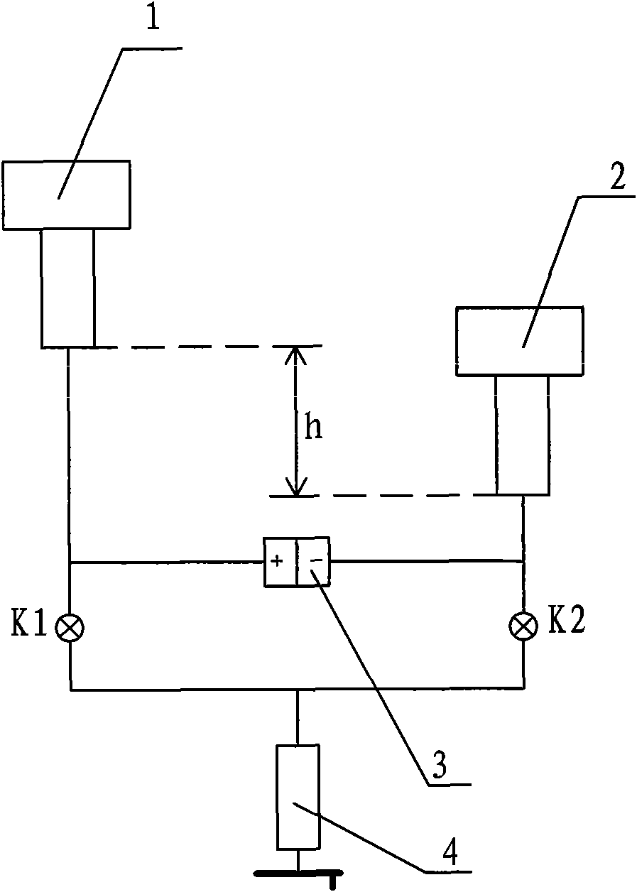
[0106] A pressure gauge effective area measuring device, such as figure 2 As shown, it is applied to the determination of the effective area of a piston pressure gauge, including a standard piston 1, a tested piston 2, a pressure source 4, and a differential pressure measurement device 3. The differential pressure measurement device 3 is a differential pressure transmitter 3, where the standard Piston 1 is connected to the positive pressure end of the differential pressure transmitter, and is connected to the pressure source 4 through the first valve K1; the tested piston 2 is connected to the negative pressure end of the differential pressure transmitter, and is connected to the pressure source through the second valve K2. Source 4 is connected.
[0107] Due to the different piston structures, the lower end surface of piston 1 is higher than the lower end surface of piston 2 by h.
[0108] The app...
PUM
 Abstract
Description
Claims
Application Information
 - R&D
- Intellectual Property
- Life Sciences
- Materials
- Tech Scout
- Unparalleled Data Quality
- Higher Quality Content
- 60% Fewer Hallucinations
Browse by: Latest US Patents, China's latest patents, Technical Efficacy Thesaurus, Application Domain, Technology Topic, Popular Technical Reports.
© 2025 PatSnap. All rights reserved.Legal|Privacy policy|Modern Slavery Act Transparency Statement|Sitemap|About US| Contact US: help@patsnap.com