Universal optical antenna of synthetic aperture laser imaging radar

A technology of synthetic aperture laser and radar optics, applied in the field of synthetic aperture laser imaging radar, can solve the problem of inability to adjust the transmitting wave surface and receiving field of view, without considering the aberration wavefront shape of the optical antenna receiving wave surface, and without considering the additional space of the optical antenna. Sub-item phase offset and other issues to achieve the effect of eliminating aberrations, realizing aperture synthesis imaging, and realizing receiving directionality

Active Publication Date: 2009-07-08
SHANGHAI INST OF OPTICS & FINE MECHANICS CHINESE ACAD OF SCI
View PDF0 Cites 12 Cited by
  • Summary
  • Abstract
  • Description
  • Claims
  • Application Information

AI Technical Summary

Problems solved by technology

[0004] Synthetic aperture laser imaging was first verified in the laboratory, but these experiments belonged to the close-range simulation of small beams, and did not use real optical telescopes as receiving and transmitting antennas
In 2006, with the support of the US Defense Advanced Research Projects Agency, Raytheon and Northrop Grumman respectively realized airborne synthetic aperture lidar experiments, but did not consider the influence of the receiving wavefront aberration or wavefront shape of the optical antenna, and did not Considering the additional spatial quadratic term phase offset when transmitting from an optical antenna
However, this optical antenna is only suitable for a specific working distance, which can be far field or near field, but cannot adjust the transmitting wave surface and receiving field of view

Method used


Image

  • Universal optical antenna of synthetic aperture laser imaging radar
  • Universal optical antenna of synthetic aperture laser imaging radar
  • Universal optical antenna of synthetic aperture laser imaging radar

Examples


Embodiment Construction

[0031] The present invention will be further described below in conjunction with the embodiments and accompanying drawings, but the protection scope of the present invention should not be limited thereby.

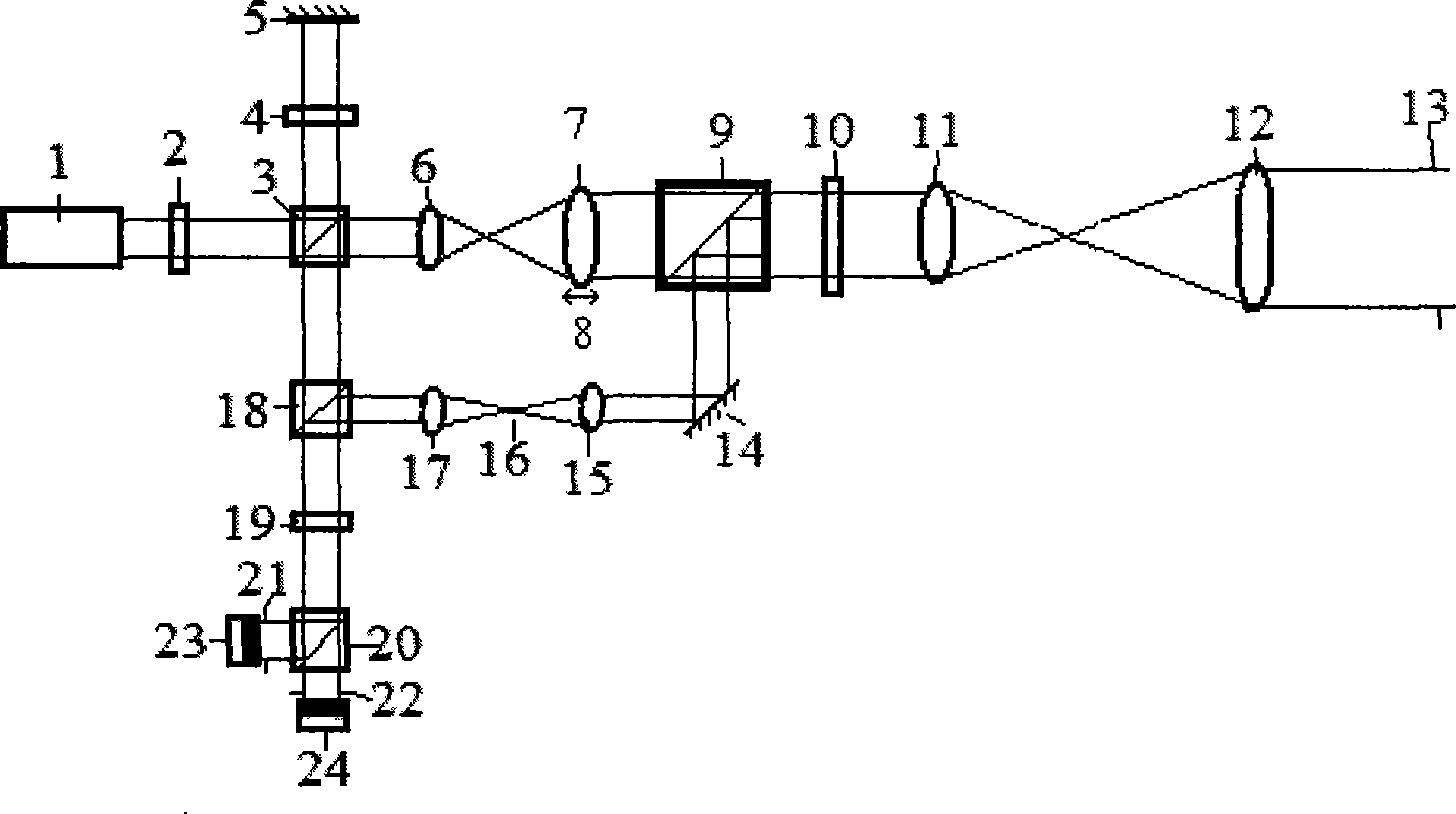
[0032] see first figure 1 , figure 1 It is a system diagram of a general synthetic aperture laser imaging radar optical antenna embodiment of the present invention.

[0033] The laser light source 1 of the synthetic aperture laser imaging radar emits a laser beam through the first half-wave plate 2 and the first polarization beam splitter 3, and the path reflected by the first polarization beam splitter 3 is used as a local oscillator laser beam through the first quarter The wave plate 4 arrives after being returned by the first reflector 5 and passes through the first polarization beam splitter 3 to output the local vibrating laser beam to the third polarization beam splitter 18, and the first polarization beam splitter 3 transmits the light beam as the emitted laser beam...


PUM


Abstract

The invention provides a universal synthetic aperture laser imaging radar optical antenna for transmitting and receiving a distant-field or near-field optical signal for the same synthetic aperture laser imaging radar system. The antenna transmits and receives a primary telescope by a bidirectional loop, wherein the bidirectional loop consists of a transmitting channel of an adjustable secondary telescope structure and a receiving channel of an erecting telescope structure, and is connected with a laser light source, a photoelectric detector and the primary telescope; the position of a primary mirror of the secondary telescope in the transmitting channel can be moved; erecting system defocusing is arranged in the receiving channel; and a variable aperture light diaphragm is arranged in front of the photoelectric detector. The universal synthetic aperture laser imaging radar optical antenna can realize a laser transmitting wave surface with different curvature radiuses additively offset through special quadratic phase by controlling the moving distance of transmitting the secondary telescope, and can realize adjustment of receiving directivity of the optical antenna by controlling defocusing amount of the receiving channel and size of the aperture light diaphragm while eliminating target echo received wave surface aberration.

Description

technical field [0001] The invention relates to a synthetic aperture laser imaging radar, in particular to a general synthetic aperture laser radar optical antenna. [0002] A two-way loop transmitting and receiving telescope is adopted. The two-way loop is composed of the transmitting channel of the adjustable sub-telescope structure and the receiving channel of the relay-image telescope structure, and connects the laser light source, the photodetector and the main telescope. The position of the primary mirror of the secondary telescope in the transmitting channel can be moved, the defocusing system of the image transfer system is set in the receiving channel, and the aperture diaphragm is placed in front of the photodetector. By controlling the position of the objective lens of the transmitting sub-telescope, the present invention can realize the laser transmitting wavefront with additional offset of the phase of the quadratic term of the space with different curvature radi...

Claims


Application Information

Patent Timeline
Patent Type & Authority Applications(China)
IPC IPC(8): G01S7/481G01S17/89G02B23/00
Inventor 闫爱民刘立人周煜孙建锋
Owner SHANGHAI INST OF OPTICS & FINE MECHANICS CHINESE ACAD OF SCI
Why Eureka
Try Eureka