Apparatus, method and system for antenna alignment

An antenna and receiving power technology, which is applied in the field of communication transmission, can solve the problems of cumbersome antenna adjustment methods, high labor costs, and high labor costs, and achieve the effects of reducing labor costs, lowering requirements, and ensuring network quality

Active Publication Date: 2009-07-08
HUAWEI TECH CO LTD
View PDF0 Cites 43 Cited by
  • Summary
  • Abstract
  • Description
  • Claims
  • Application Information

AI Technical Summary

Problems solved by technology

[0003] During the research process, the inventor found that the antenna adjustment method in the prior art is cumbersome, and the voltage signal needs to be tested while adjusting the antenna. Usually, two people are required to cooperate to complete it. One person is responsible for keying the instrument and checking data, and the other is responsible for Adjusting the antenna requires a lot of manpower
If it is done by one person, it is necessary to repeatedly test the data and adjust the antenna repeatedly, and the debugging efficiency is lower, which requires relatively high labor costs

Method used


Image

  • Apparatus, method and system for antenna alignment
  • Apparatus, method and system for antenna alignment
  • Apparatus, method and system for antenna alignment

Examples


Embodiment Construction

[0014] In order to make it easier for those skilled in the art to understand and realize the present invention, the embodiments of the present invention are described in conjunction with the accompanying drawings. Here, the exemplary embodiments and descriptions of the present invention are used to explain the present invention, but not to limit the present invention.

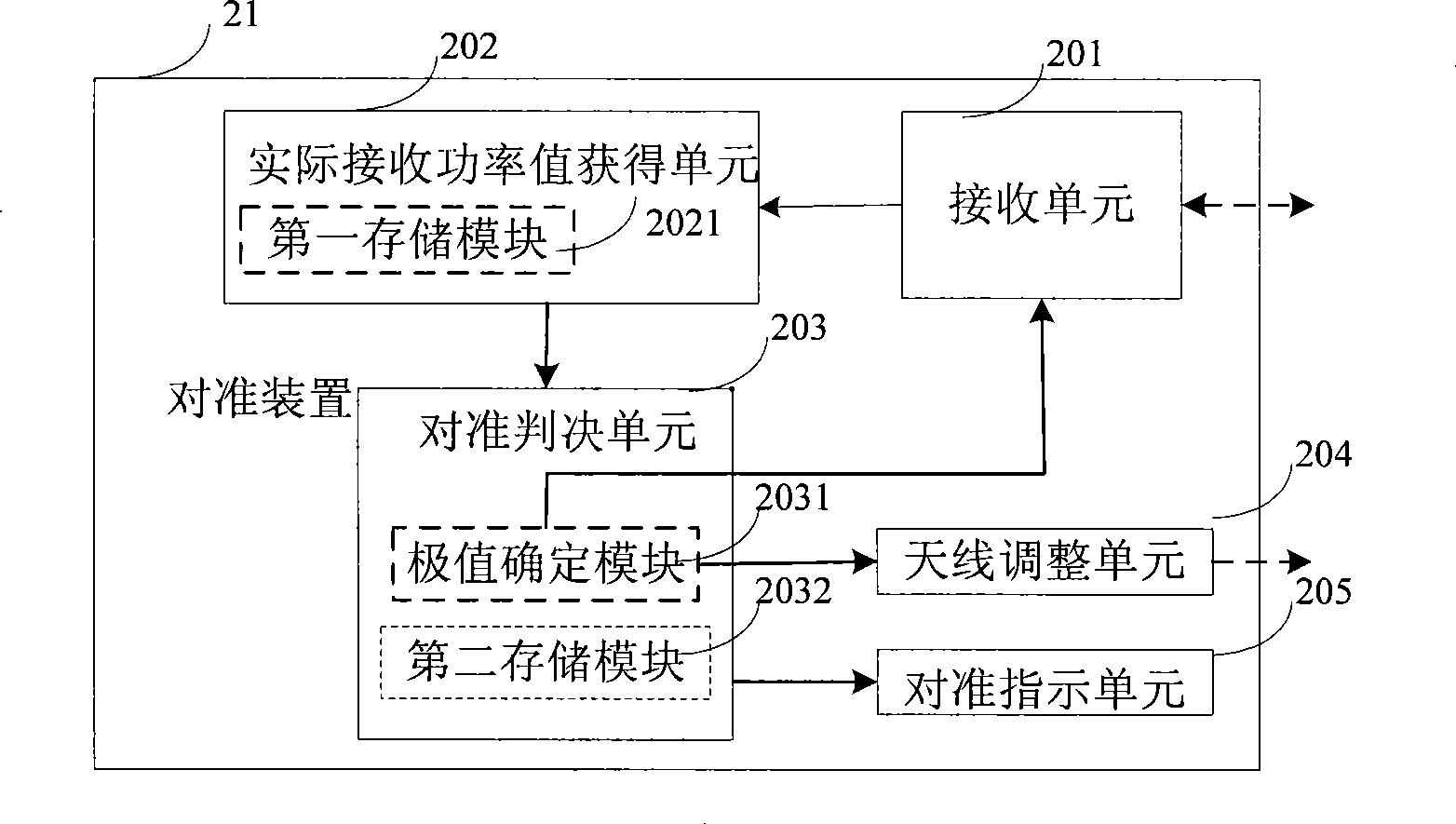
[0015] The structure of the antenna alignment device in the embodiment of the present invention is as follows figure 2 As shown, the alignment device 21 includes: a receiving unit 201, an actual received power value obtaining unit 202, an alignment decision unit 203, an antenna adjustment unit 204, an alignment indication unit 205,

[0016] The receiving unit 201 is configured to receive an input signal, and output an RSSI value according to the magnitude of the input signal;

[0017] The actual received power value obtaining unit 202 is used to receive the RSSI value, and obtain the actual received power val...


PUM


Abstract

The invention relates to the field of communication and transmission, and particularly discloses a device, a method and a system for antenna alignment. The method comprises the following steps: receiving an input signal and outputting a received signal strength indicator (RSSI) according to the input signal; receiving the RSSI and acquiring the actual received power value relative to the input signal by searching the RSSI and the power correspondence table; and comparing the actual received power value relative with the theoretic received power threshold value, and when the actual received power value is less than the theoretic received power threshold value, outputting an antenna rotation signal; when the actual received power value is more than or equal to the theoretic received power threshold value, outputting an alignment indication signal; adjusting an antenna to change the receiving angle of the antenna according to the antenna rotation signal; and aligning the antenna according to the alignment indication signal. The method reduces the artificial operation error and effectively ensures the network quality.

Description

technical field [0001] The present invention relates to the field of communication transmission, in particular to an antenna alignment device, method and system. Background technique [0002] In a microwave system, the structure schematic diagram of the antenna alignment device in the prior art is shown as figure 1 As shown in the figure, it is divided into indoor unit, outdoor unit and antenna. The indoor unit and outdoor unit are installed separately and connected by an intermediate frequency cable. For normal communication between two microwave sites, the antennas must be aligned, so as to ensure normal transmission and reception of signals between microwave sites. For antenna alignment, the prior art method is to design a received power level indication interface on the outdoor unit, and the interface outputs a voltage signal proportional to the received power. Such as figure 1 Shown: The outdoor unit of the microwave system outputs RSSI (Receiver Signal Strength Indi...

Claims


Application Information

Patent Timeline
Patent Type & Authority Applications(China)
IPC IPC(8): H04B7/10H04B7/02
CPCH01Q1/1257
Inventor 赵贵学
Owner HUAWEI TECH CO LTD
Why Eureka
Try Eureka