Improved 802.11 mesh architecture

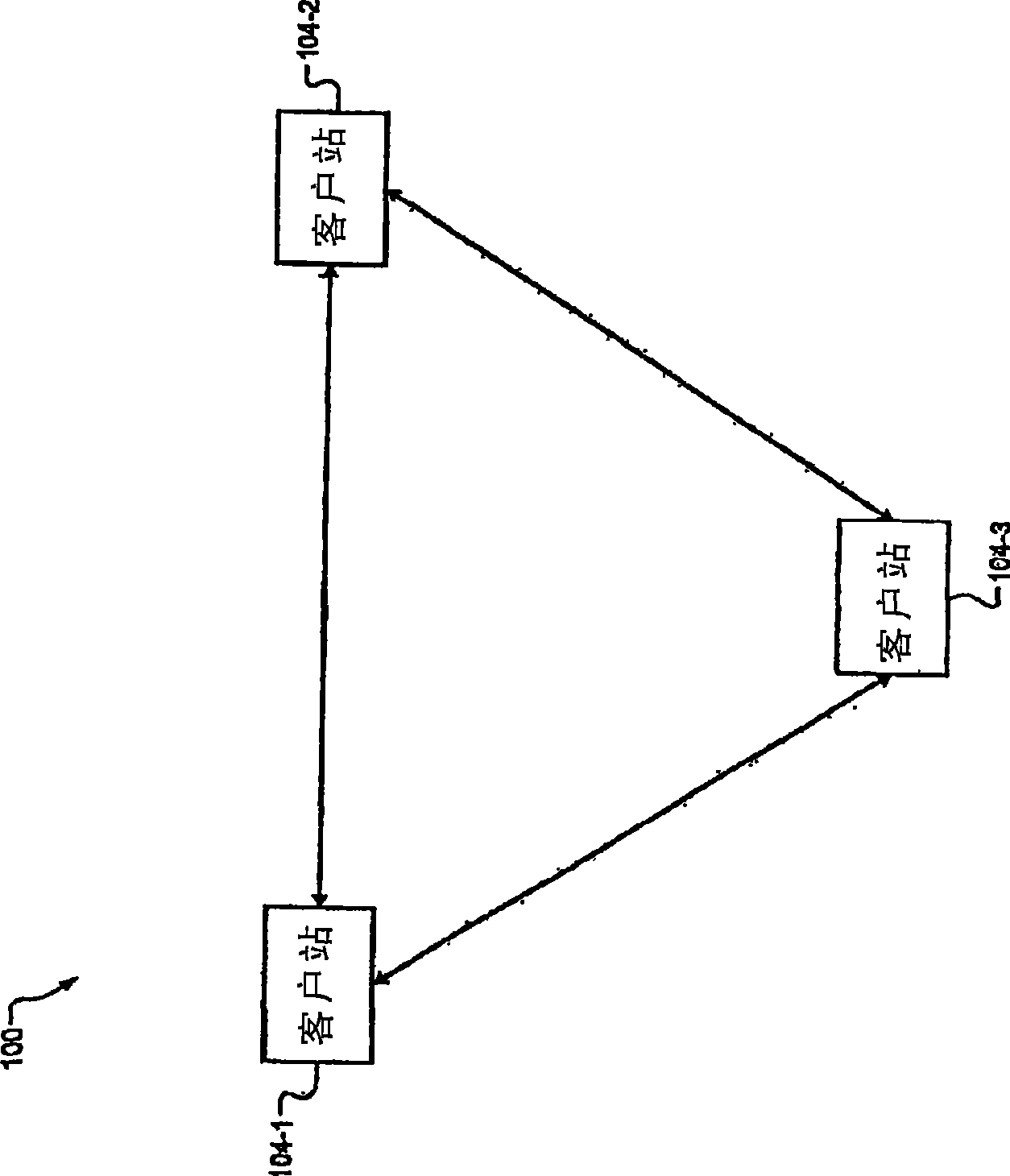
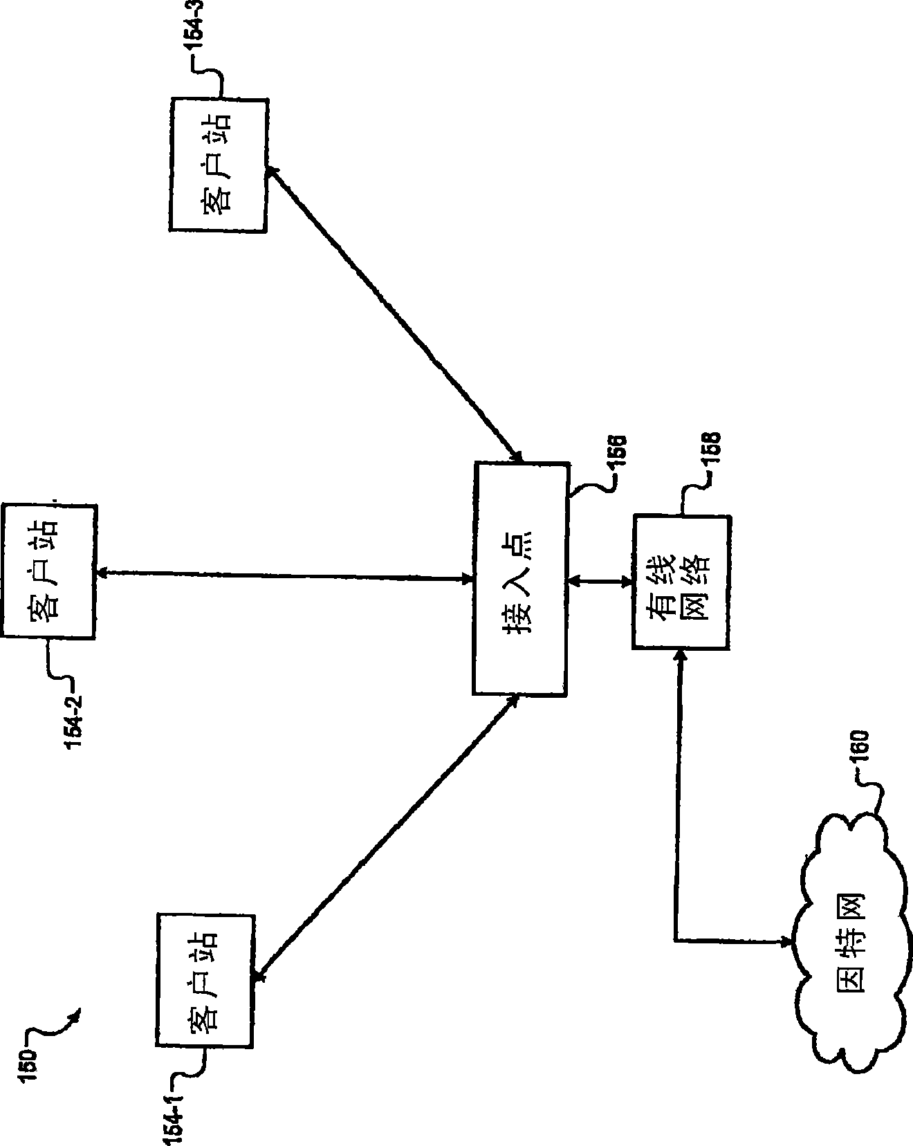
A grid and destination technology, applied in the transmission system, network topology, digital transmission system, etc., can solve the problem that the client station 104 cannot send or receive data, etc.

Active Publication Date: 2009-07-08
MARVELL ASIA PTE LTD
View PDF4 Cites 13 Cited by
  • Summary
  • Abstract
  • Description
  • Claims
  • Application Information

AI Technical Summary

Problems solved by technology

[0007] Client station 104 may not be able to

Method used


Image

  • Improved 802.11 mesh architecture
  • Improved 802.11 mesh architecture
  • Improved 802.11 mesh architecture

Examples


Embodiment Construction

[0113] The following description is merely exemplary in nature and is in no way intended to limit the disclosure, its application, or uses. For purposes of clarity, the same reference numbers will be used in the drawings to identify similar elements. As used herein, the phrase "at least one of A, B, and C" should be construed to mean a logical (A or B or C) using a non-exclusive logical or. It should be understood that steps within a method may be executed in different order without altering the principles of the present disclosure.

[0114] As used herein, the term "module" refers to an application-specific integrated circuit (ASIC), an electronic circuit, a processor (shared, dedicated or group) and memory that executes one or more software or firmware programs, a combinational logic circuit, and / or Other suitable components that provide the described functionality.

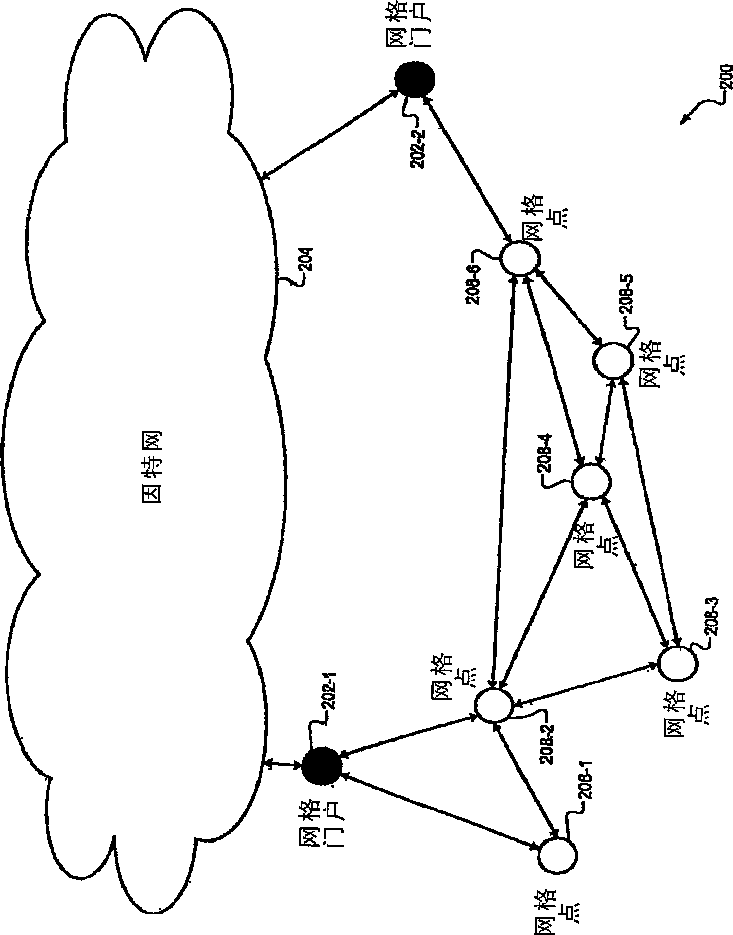
[0115] now refer to Figure 4 , which presents a functional block diagram of an exemplary mesh network 250...


PUM


Abstract

A wireless network device comprises a forwarding table and a mesh routing module. The forwarding table stores direct and reverse entries, each including a destination address, a next hop address, and a metric. The metric of the direct entries corresponds to a route from the wireless network device to the destination address. The metric of the reverse entries corresponds to a route from the destination address to the wireless network device. The mesh routing module wirelessly receives route discovery packets and creates corresponding entries in the forwarding table.

Description

technical field [0001] The present disclosure relates to wireless mesh networks. Background technique [0002] The background description provided herein is for the purpose of generally presenting the context of the disclosure. The work of the presently named inventors described in this Background section, as well as aspects of the description that were not considered prior art at the time of filing, are not expressly or implicitly admitted to be prior art to the present disclosure. [0003] IEEE 802.11, 802.11a, 802.11b, 802.11g, 802.11h, 802.11n, 802.16, and 802.20, which are hereby incorporated by reference in their entirety, define the operation and implementation of wireless local area networks (WLANs). These standards define the operation mode of WLAN, including self-organizing mode and infrastructure mode. [0004] Referring now to FIG. 1 , a functional block diagram of an ad hoc wireless network 100 is shown. Ad hoc wireless network 100 includes three wireless cli...

Claims


Application Information

Patent Timeline
IPC IPC(8): H04L12/56H04L45/02H04L45/74H04W40/10H04W40/24
CPCH04W40/10H04W40/246H04L45/26H04L45/54H04W84/18Y02D30/70H04B7/24H04L12/28H04W88/02
Inventor 哈加·巴内杰亚桑代什·戈尔
Owner MARVELL ASIA PTE LTD
Why Eureka
Try Eureka