
Color liquid crystal display device and image display method thereof

a liquid crystal display and liquid crystal display technology, applied in the field of liquid crystal display devices, can solve the problems of inability to display color images in prior art lcd devices, and achieve the effect of improving the displayability of color images in lcd devices

Inactive Publication Date: 2005-06-09
SEMICON ENERGY LAB CO LTD
View PDF19 Cites 2 Cited by
  • Summary
  • Abstract
  • Description
  • Claims
  • Application Information

AI Technical Summary

Benefits of technology

[0009] It is another object of the invention to provide an improved color image displayable LCD device while permitting direct entry of necessary data or instructions by use of an associated touch-sensitive pointing input device.
[0010] It is yet another object of the invention to provide an improved method of displaying color images on LCD devices while permitting direct entry of input data or instructions using an associated touch-sensitive pointer.
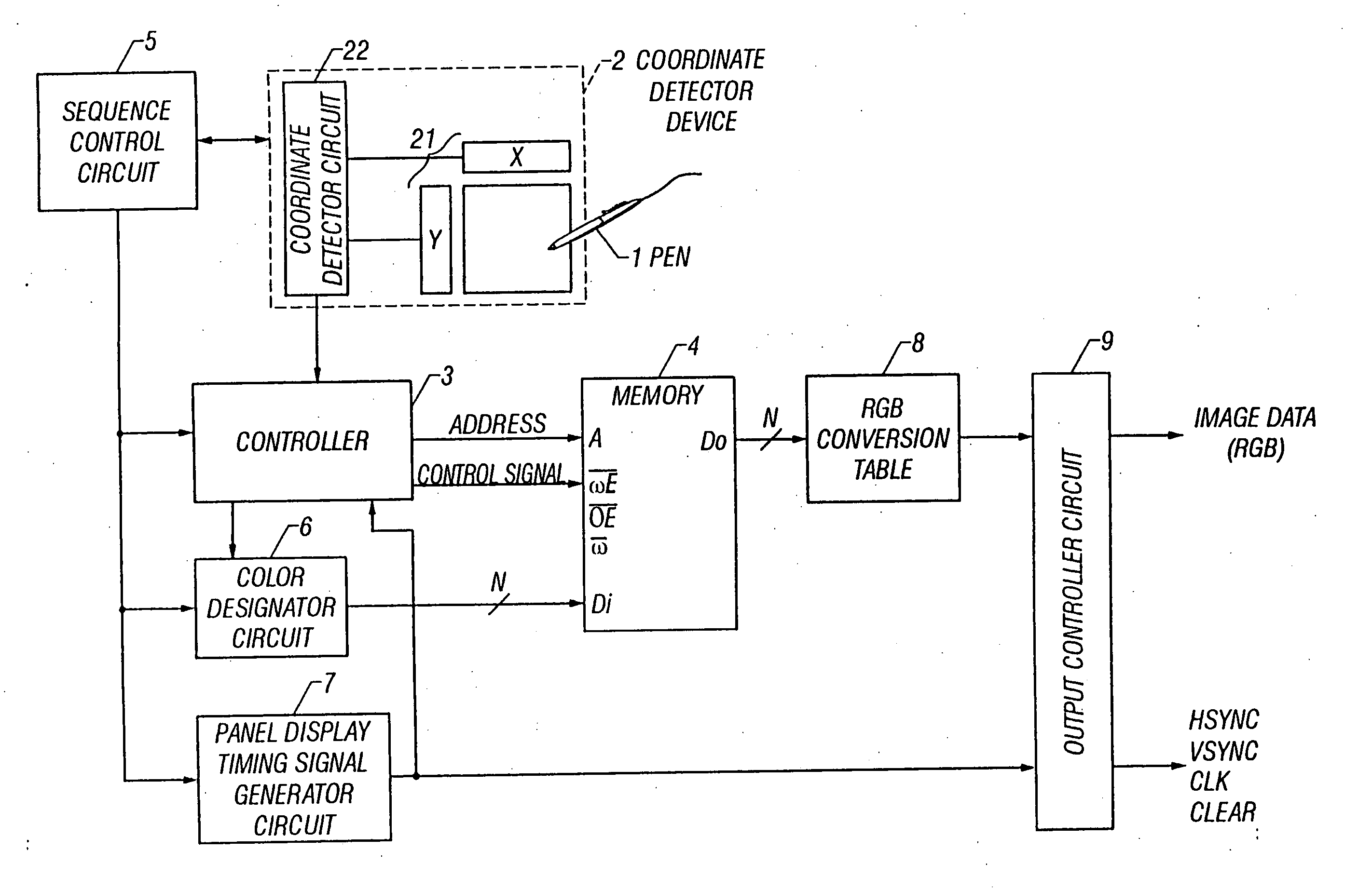
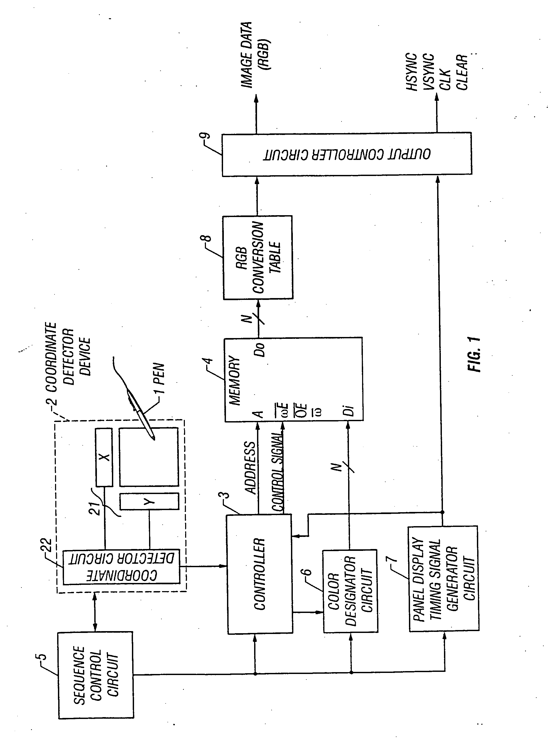
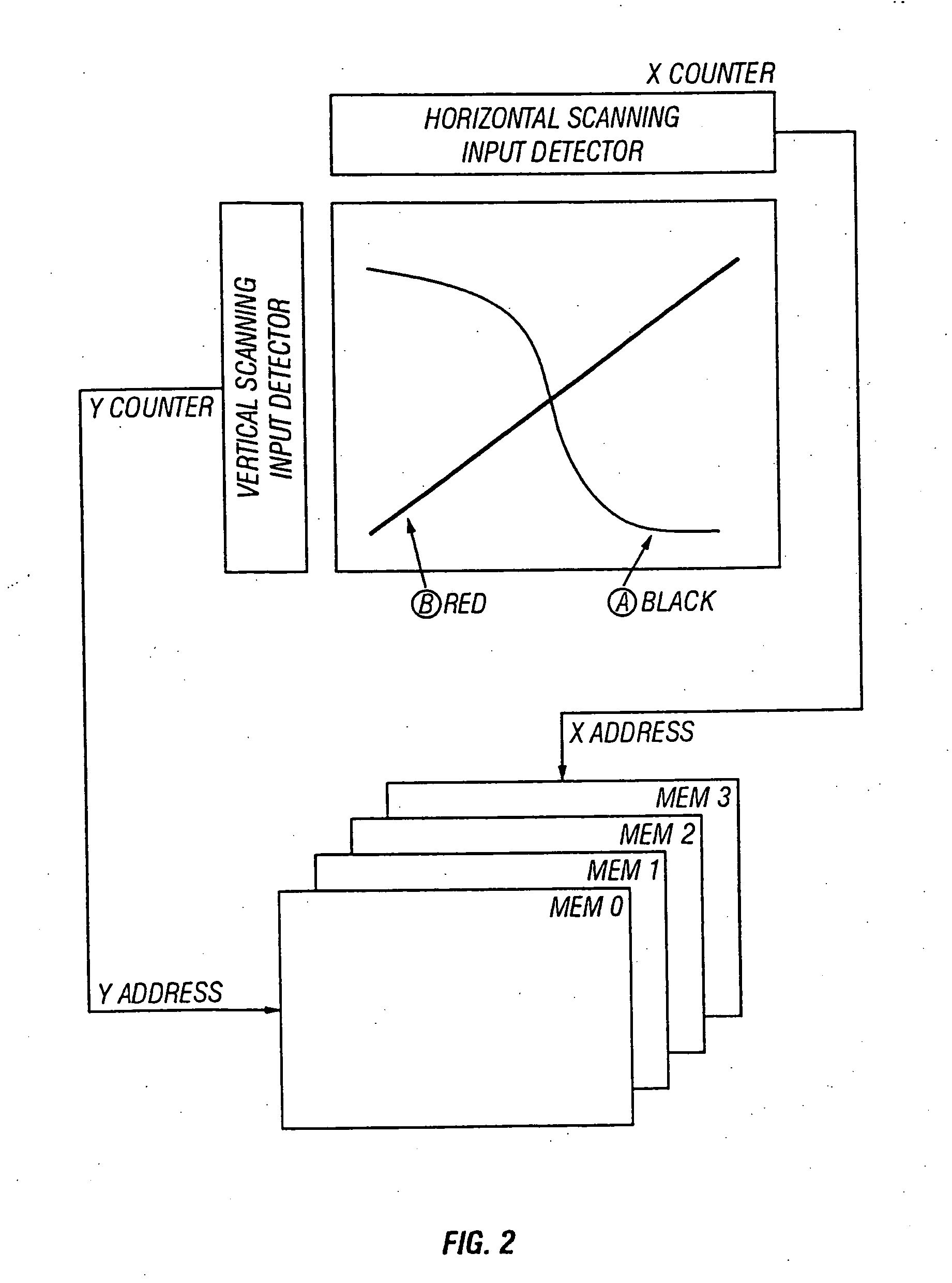
[0019] A storage controller unit is responsive to receipt of the resulting coordinate data for generating and issuing an address selected. Based on the address, the controller also serves to control read / write operations of color data with respect to a memory associated. The color data stored in the memory is then read out under the control of the storage controller to be supplied as video data to the display panel. In this way, it becomes possible to display a color image by use of pen input device.

Problems solved by technology

Unfortunately, the prior art LCD devices suffer from the lack of ability to process color images for display.

Method used


Image

  • Color liquid crystal display device and image display method thereof
  • Color liquid crystal display device and image display method thereof
  • Color liquid crystal display device and image display method thereof

Examples


Embodiment Construction

[0026] Referring to FIG. 1, a liquid crystal display (LCD) device in accordance with one preferred embodiment of the invention includes an LCD panel with a matrix of rows and columns of picture elements or “pixels,” which may also be called the “dots” in some cases. The LCD panel comes with a coordinate detector device 2 for detection of coordinates as input by an associated pen-shaped touch-sensitive pointing input device known as an “input pen” or “pen pointer” in the art. Here, the LCD panel is of the active-matrix type which may be configured as shown in FIG. 5. As shown, the active-matrix LCD panel incorporates a matrix of pixels, each of which is at a corresponding one of cross points or intersections between horizontal scanning lines 52 and vertical signal transmission lines 53. The individual pixel includes therein a switch element 50, which selectively turns on and off controlling adequate transfer of image information to an associative display medium. This medium may be a ...


PUM

PropertyMeasurementUnit
coloraaaaaaaaaa
colorsaaaaaaaaaa
sizeaaaaaaaaaa

Abstract

There is disclosed a color liquid crystal display (LCD) device capable of displaying color images in response to direct entry of input data and / or instructions through operation of an associated coordinate pointing tool. Typically, this tool is a pen-like input device known as the “input pen” for use in determining the individual position for color display on the screen of a built-in LCD panel. A coordinate detector operates to recognize the position as designated by the input pen, generating and issuing an output signal indicative of the corresponding coordinate data. A color designator circuit designates a color as presently selected for color display. A memory device stores therein color data representative of the color designated. A memory controller is responsive to receipt of an address issued from the selected coordinate data for controlling the color data to be written into and read out of the memory. An output controller allows the color data read from the memory to be supplied to the LCD display screen as video data.

Description

[0001] This application is a continuation of U.S. application Ser. No. 08 / 725,642 filed Oct. 15, 1996. The disclosure of the above application is incorporated herein by reference as part of this application.BACKGROUND OF THE INVENTION [0002] 1. Field of the Invention [0003] The present invention relates generally to liquid crystal display (LCD) devices, and more particularly to color LCD devices for use with a touch-sensitive pointing input device and an image display method thereof. [0004] 2. Description of the Prior Art [0005] Through the trend of complexity in computerization as to diversity of information in the recent past, portable or “handheld” electronic information management tools including personal digital assistants (PDAs) have found increasing applications due to advantages such as small size and light weight. In the thrust to achievement of such advanced handheld information management tools, the pen-input scheme is becoming more important for permission of direct entr...

Claims


Application Information

Patent Timeline
Patent Type & Authority Applications(United States)
IPC IPC(8): G02F1/133G06F3/041G06F3/048G09G3/36
CPCG06F3/041G06F3/0412G06F3/0488G09G5/36G09G3/3648G09G5/022G06F3/04883
Inventor HIRAKATA, YOSHIHARU
Owner SEMICON ENERGY LAB CO LTD
Learn More