
Cognitive system channel state configuration method, detection management device, and base station

A technology for channel status and equipment management, applied in the transmission system, communication between multiple stations, transmission monitoring, etc., can solve problems such as signal interference, occupancy, and incomplete understanding of channel occupancy, and achieve a reasonable allocation effect

Inactive Publication Date: 2009-07-15
广东高航知识产权运营有限公司
View PDF3 Cites 11 Cited by
  • Summary
  • Abstract
  • Description
  • Claims
  • Application Information

AI Technical Summary

Problems solved by technology

[0011] Because after analyzing the information reported by the data source, the channel occupancy situation in the coverage area of ​​the cognitive system is obtained, and then spectrum holes are found. However, in the prior art, only one channel state is stored for a channel, and this state is maintained. But in fact, due to the difference in geographical location of the occupancy sources, a channel is likely to be occupied by multiple occupancy sources at the same time, which leads to an incomplete understanding of the occupancy of the channel by the system. For example, channel K is occupied by two occupancy sources, one is One is occupied by the TV system, one is occupied by the wireless microphone
If the system only saves one piece of information that is occupied by the TV system, when the cognitive system learns that the TV system no longer occupies the K channel according to the information reported by the data source, it will consider the K channel to be idle and allocate the K channel to the cognitive system. The terminal of the system is used, but the actual wireless microphone is still occupying the channel, which will cause interference between signals, which is likely to have a greater impact on authorized users and reduce the user's service experience.

Method used


Image

  • Cognitive system channel state configuration method, detection management device, and base station
  • Cognitive system channel state configuration method, detection management device, and base station
  • Cognitive system channel state configuration method, detection management device, and base station

Examples


Embodiment 1

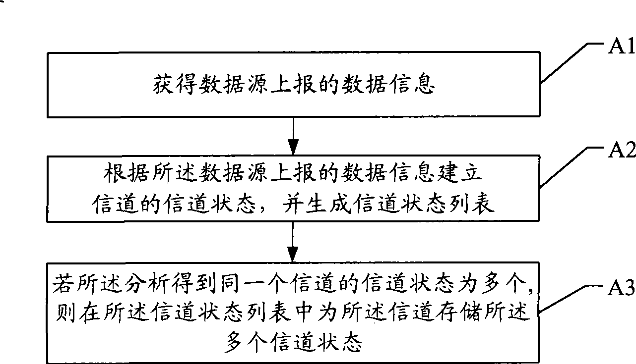
[0034] Embodiment 1, a cognitive system channel state configuration method, the flow chart is as follows figure 1 shown, including:

[0035] A1, obtain the data information reported by the data source;

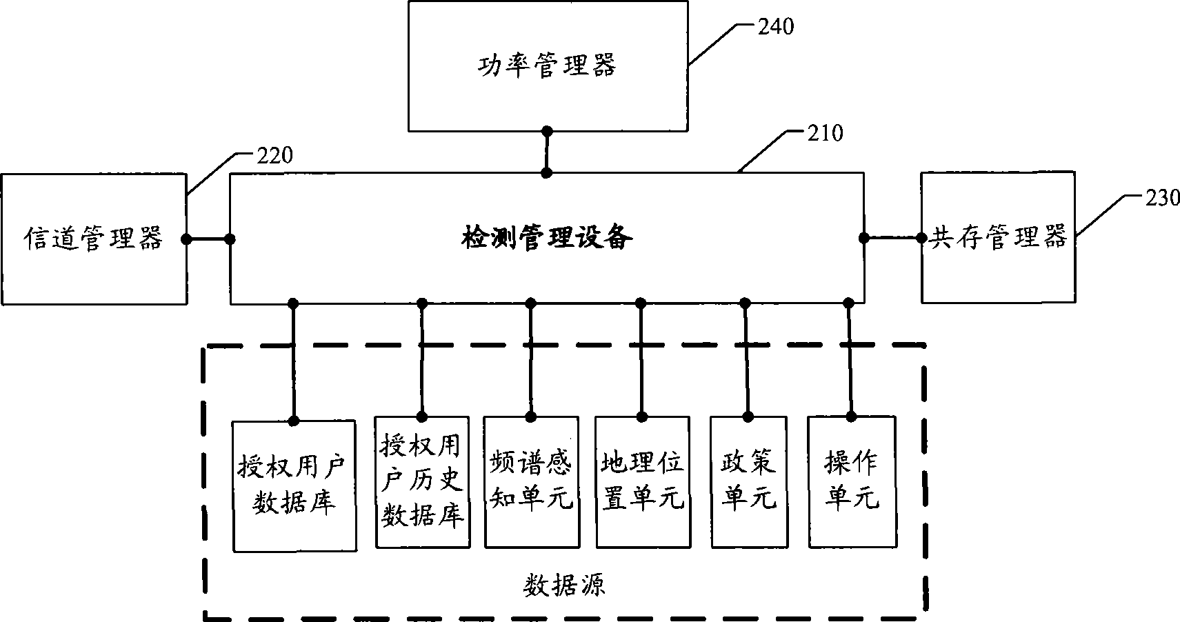
[0036] In the embodiment of the present invention, the data source may be at least one of an authorized user database, an authorized user history database, a sensing spectrum unit, a geographic location unit, and a policy unit.

[0037] It can be understood that, depending on the data source, the type and format of the data information reported by the data source can also be different, but they are all relevant parameters for analyzing the channel state. The present invention emphasizes that the information reported by the data source can be Analyze the state of the channel.

[0038] A2, analyzing the channel state of the channel according to the data information reported by the data source, and generating a channel state list;

[0039] In the embodiment of the present inve...

Embodiment 3

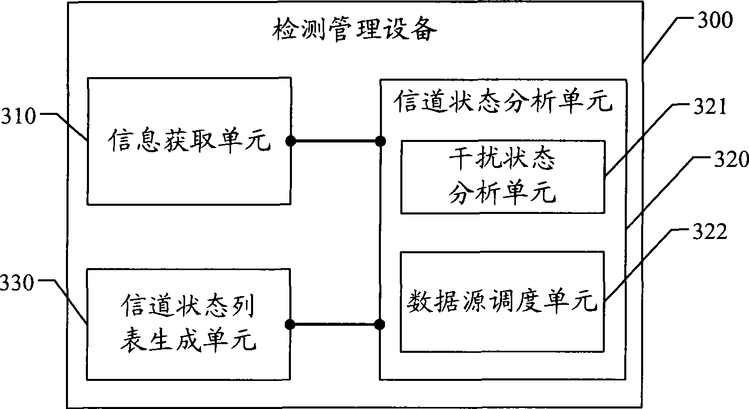
[0130] Embodiment 3 of the present invention, a detection management device 300, the structure diagram is as follows image 3 As shown, it includes: an information acquisition unit 310, a channel state analysis unit 320, and a channel state list generation unit 330;

[0131] The information obtaining unit 310 is configured to obtain data information reported by a data source;

[0132] The channel state analysis unit 320 analyzes the channel state of the channel according to the data information reported by the data source obtained by the information acquisition unit 310;

[0133] The channel state list generation unit 330 is configured to generate a channel state list according to the channel state analyzed by the channel state analysis unit 320, if the analysis results in multiple channel states of the same channel; then in the channel state list The plurality of channel states are stored for the channel.

[0134] In this embodiment, the state of the channel includes an int...

Embodiment 4

[0141]Embodiment 4, a detection and management device, the structural diagram is as follows Figure 4 As shown, it includes: an information acquisition unit 410, a channel state analysis unit 420, a channel state list generation unit 430, and a channel state list output interface unit 440; the channel state analysis unit 420 includes: an interference state analysis unit 421 and a data source scheduling unit 422;

[0142] An information obtaining unit 410, configured to obtain data information reported by a data source;

[0143] The channel state analysis unit 420 analyzes the channel state of the channel according to the data information reported by the data source obtained by the information acquisition unit 410;

[0144] The channel state list generation unit 430 is used to generate a channel state list according to the channel state analyzed by the channel state analysis unit 420, if the analysis shows that there are multiple channel states of the same channel; The channe...


PUM


Abstract

An embodiment of the invention discloses a method for collocating channel state of cognitive system, a detection management device and a base station. The method of the invention comprises the following steps: obtaining data information reported by the data source; analyzing the channel state of channel according to the data information reported by the data source; and if a plurality of channel states of a same channel obtained by analyzing are obtained, storing the plurality of channel states for the channel. Because when the plurality of states exist in the channel, the existing states are saved and the actual state of empty-opening channel is actually reflected. Compared with the prior art, the states of mutual signal interference and further the interference to the authorized subscriber, which are caused by no saving of the plurality of channel states, are effectively prevented. The allocation of empty-opening resource is caused to more reasonably.

Description

technical field [0001] The present invention relates to cognitive radio technology, in particular to a cognitive system channel state configuration method, a detection management device and a base station. Background technique [0002] Cognitive radio technology is a technology that realizes efficient and flexible use of spectrum holes without interfering with authorized users. A spectrum hole is an unoccupied frequency band in a certain time and space. Due to the scarcity of radio resources and the low utilization rate of authorized frequency bands, cognitive radio technology has received extensive attention in academia and industry. [0003] The premise of the cognitive system is to be able to obtain the spectrum usage and be able to find the spectrum holes in it. The cognitive system provides a variety of data sources in order to realize the correct recognition of the spectrum. By analyzing the channel state information reported by the data sources, the spectrum holes i...

Claims


Application Information

Patent Timeline
IPC IPC(8): H04B17/00H04B7/26H04B17/382
Inventor 刘劲楠冯淑兰
Owner 广东高航知识产权运营有限公司
Learn More