Transmission method and apparatus for code on uplink control channel
A technology of control channels and transmission methods, applied in multi-frequency code systems, communication between multiple stations, etc. Interference, to achieve the effect of randomization of interference
- Summary
- Abstract
- Description
- Claims
- Application Information
AI Technical Summary
Problems solved by technology
Method used
Image
Examples
no. 4 approach
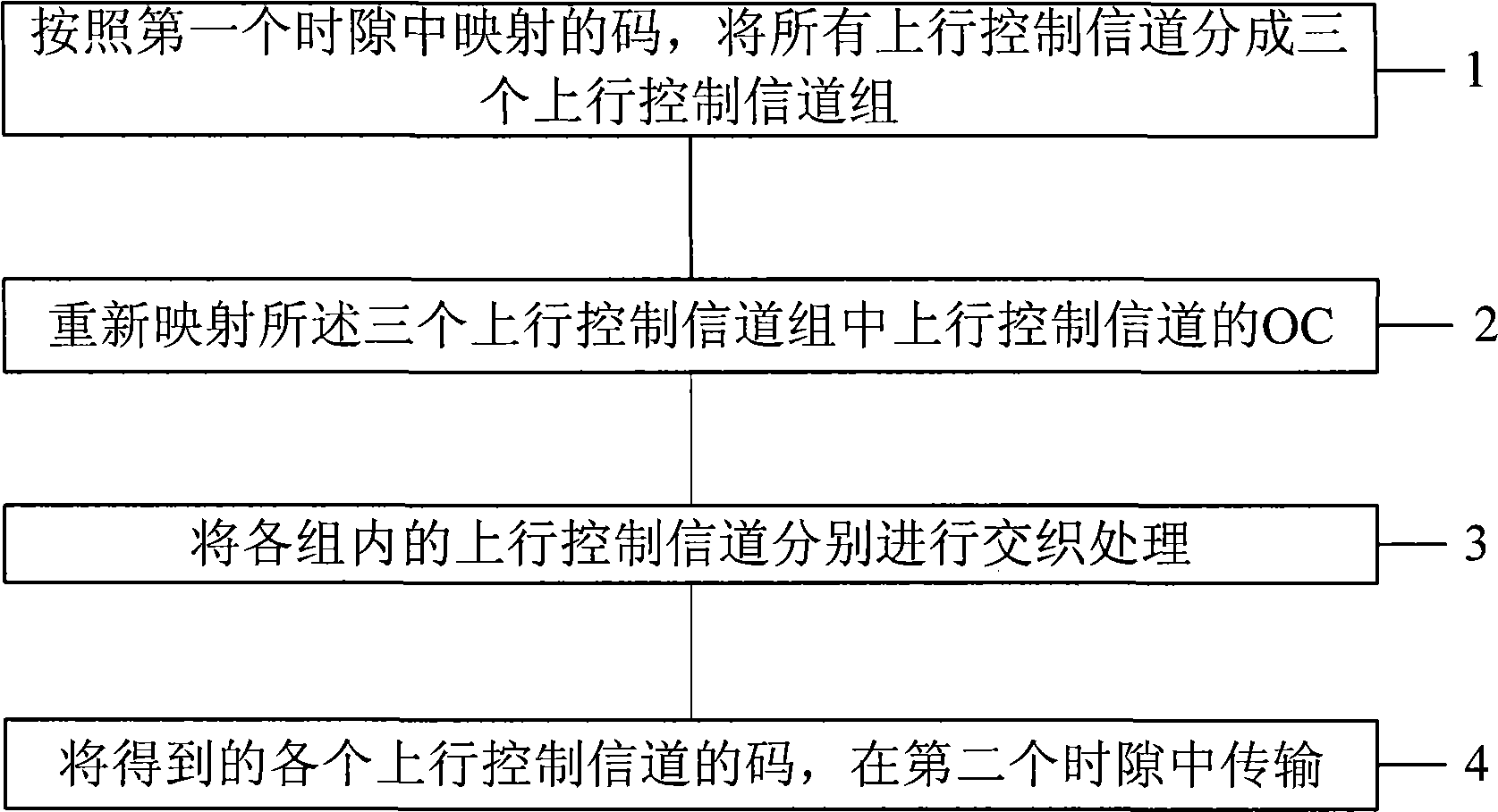
[0110] The fourth embodiment of the present invention includes the following steps:
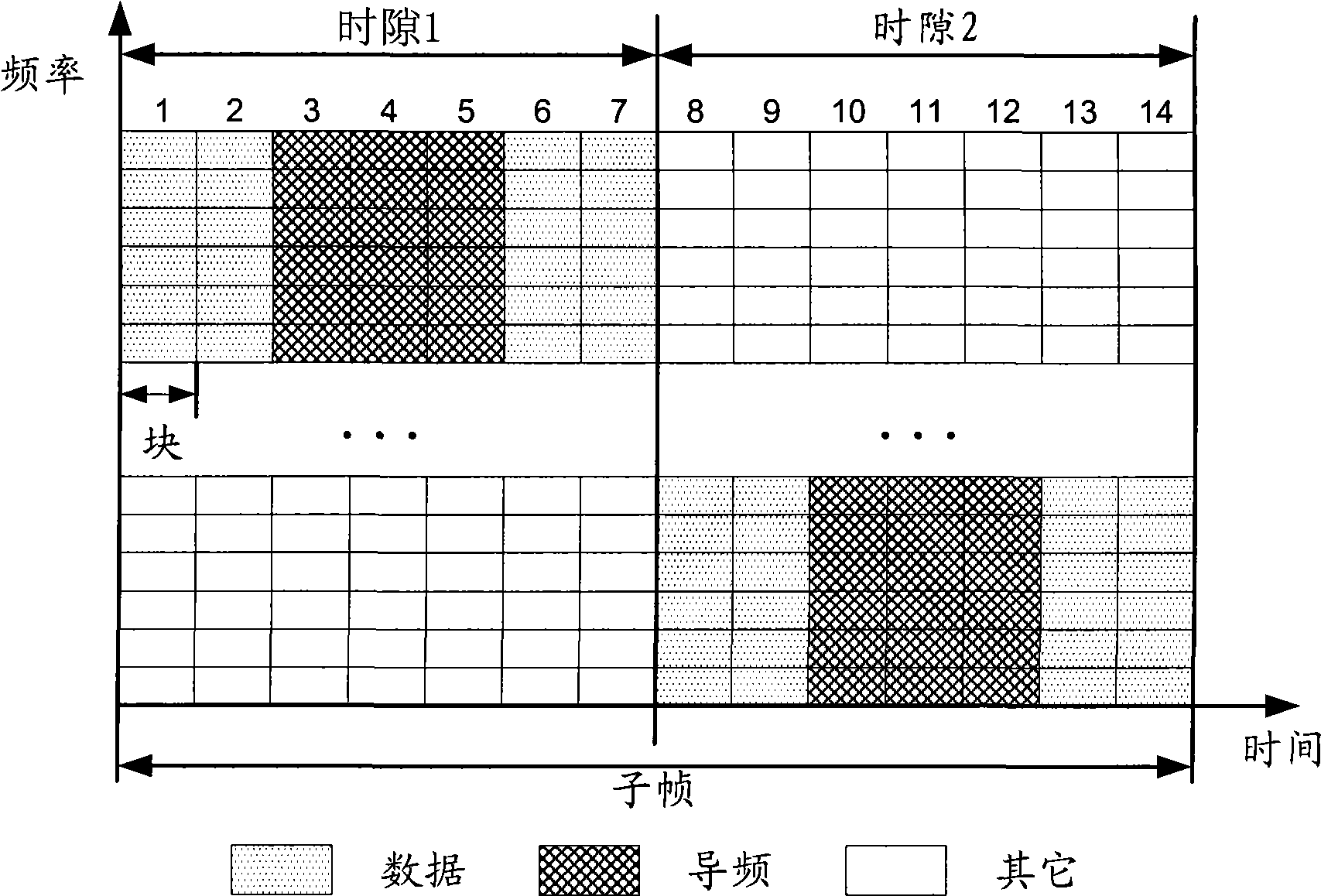
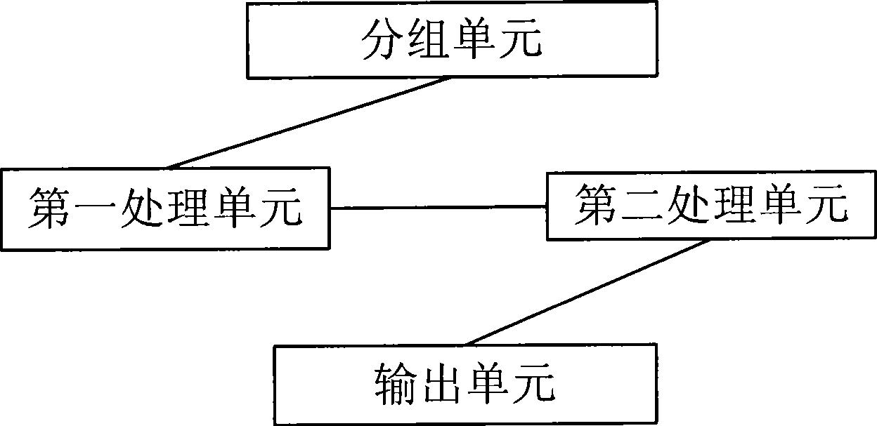
[0111] Step 1, divide all uplink control channels into at least two uplink control channel groups according to the code mapped in the first time slot;
[0112] Step 2, remapping the inter-block spreading code OC of the uplink control channel in the at least two uplink control channel groups, so that any two of the uplink control channel groups exchange the inter-block spreading code;
[0113] Step 3, performing interleaving processing on the uplink control channels in each group to obtain the codes of each uplink control channel;
[0114] Step 4, transmit the obtained codes of each uplink control channel in the second time slot.
[0115] The specific implementation of the fourth real-time mode is described in detail below,
[0116] Step 1, divide all uplink control channels into k uplink control channel groups according to the code mapped in the first time slot, wherein k is 2 or 3;
[011...
Embodiment 1
[0125]Embodiment 1, N=18 codes (CS / OC combinations) available for uplink control channels are shown in Table 9:
[0126] Table 9
[0127]
[0128] Among them, if k=3, n=3, m=1, the following table can be obtained from formula 1
[0129] 1
0
1
2
3
4
5
6
7
8 9 10 11 12 13 14 15 16 17 g(i) 8 11 7 10 6 9 2 5 1 4 0 3 14 17 13 16 12 15
[0130] That is, if a control channel is mapped to code (CS / OC combination) 0 in the above table in the first time slot, then it is remapped to the code in the above table (CS / OC combination) in the second time slot 8, and so on.
[0131] The CS / OC mapping relationship of the 18 uplink control channels on the first block of each of the two time slots is shown in Table 10, where the code on the first block of the first time slot is on the left (CS / OC combination) , the right side is the code on the first block of the second slot (CS / OC combination)...
Embodiment 2
[0163] Embodiment 2, N=12 codes (CS / OC combinations) available for uplink control channels are shown in Table 16 below:
[0164] Table 16
[0165]
[0166] If k=2, n=3, m=1, the following table can be obtained from formula 1:
[0167] i 0 1 2 3 4 5 6 7 8 9 10 11 g(i,) 8 11 7 10 6 9 2 5 1 4 0 3
[0168] That is, if a control channel is mapped to code (CS / OC combination) 0 in the above table in the first time slot, then it is remapped to the code in the above table (CS / OC combination) in the second time slot 8, and so on.
[0169] The CS / OC mapping relationship of the 18 uplink control channels on the first block of the two time slots is shown in Table 17 below, where the code on the first block of the first time slot is on the left (CS / OC combination) , the right side is the code on the first block of the second slot (CS / OC combination):
[0170] Table 17
[0171]
[0172] As can be seen from Table 17, the mapping method impl...
PUM
 Abstract
Description
Claims
Application Information
 - R&D
- Intellectual Property
- Life Sciences
- Materials
- Tech Scout
- Unparalleled Data Quality
- Higher Quality Content
- 60% Fewer Hallucinations
Browse by: Latest US Patents, China's latest patents, Technical Efficacy Thesaurus, Application Domain, Technology Topic, Popular Technical Reports.
© 2025 PatSnap. All rights reserved.Legal|Privacy policy|Modern Slavery Act Transparency Statement|Sitemap|About US| Contact US: help@patsnap.com


