Incoherent Imaging Glass Thickness Measurement Method

A non-coherent, imaging technology, applied in measurement devices, instruments, optical devices, etc., can solve the problems affecting the stability and accuracy of measurement results, laser speckle, missing light spots, etc., achieve stable spot position calculation, avoid strong interference, The effect of reducing the phenomenon of spot disappearance

Inactive Publication Date: 2016-07-06
DALIAN UNIV OF TECH
View PDF5 Cites 0 Cited by
  • Summary
  • Abstract
  • Description
  • Claims
  • Application Information

AI Technical Summary

Problems solved by technology

The reflection of the laser beam on the upper and lower surfaces of the glass is equivalent to an optical lever. The slight angle change of the glass relative to the measurement system will be amplified by the optical lever, which will easily cause the phenomenon of missing spots where the beam cannot enter the linear array CCD; the laser beam is reflected by the glass surface and enters the CCD. , will form laser speckle, making the ideal Gaussian spot into a speckle pattern with violent random changes in intensity, which seriously affects the stability and accuracy of the measurement results; in addition, the laser beam itself has a small cross-section and is easily affected by The effect of local blemishes

Method used


Image

  • Incoherent Imaging Glass Thickness Measurement Method
  • Incoherent Imaging Glass Thickness Measurement Method

Examples


Embodiment Construction

[0010] The specific embodiments of the present invention will be described in detail below in conjunction with the technical solutions and accompanying drawings.

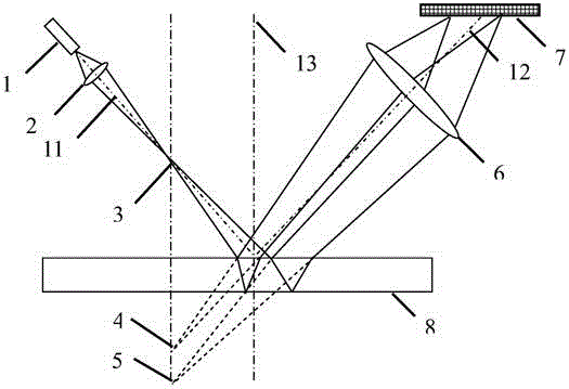
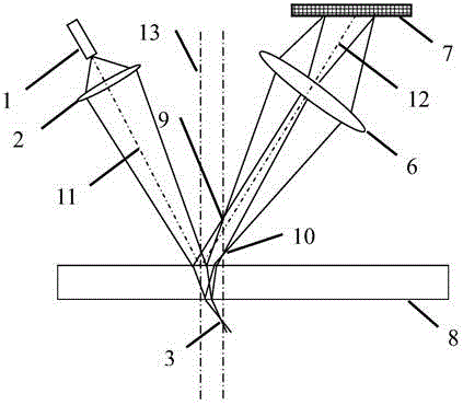
[0011] combined with figure 1 , to illustrate specific embodiments of the present invention. Use an incoherent point light source or line light source 1 to form a real image at the real image point 3 after the converging lens 2, and then the light continues to travel in a straight line to the glass plate 8 to be tested, and a small part of the light is reflected by the upper surface of the glass plate 8 to form a virtual image At the upper virtual image point 4, most of the light is refracted into the measured glass plate 8, a small part of which is reflected by the lower surface of the measured glass plate 8, and emerges from the upper surface of the measured glass plate 8 to form the lower virtual image point 5. The light reflected by the upper and lower surfaces of the measured glass plate 8 enters the imaging l...


PUM


Abstract

The invention relates to an incoherent imaging glass thickness measuring method and belongs to the technical field of photoelectrical detection. The incoherent imaging glass thickness measuring method is characterized in that an incoherent point light source or a line light source is adopted as a lighting source, if the incoherent line light source is adopted, the length direction of the line light source is required to be parallel to the surface of a detected glass board, light emitted by the lighting source passes through a converging lens and a real image is imaged above the upper surface of the detected glass board or below the lower surface of the detected glass board. An imaging lens carries out imaging of two virtual images or two real images, wherein the two virtual images or the two real images are formed as the upper surface and the lower surface of the detected glass board reflect light of the incoherent point light source or the line light source. Two imaged real image faculae are located on a light sensing face of a line array imaging device or a face array imaging device and the thickness of the detected glass board can be obtained by calculating the distance between the two faculae. The incoherent imaging glass thickness measuring method has the advantages that influences of scattered faculae are avoided, measuring stability is improved, the probability of missing of the faculae due to angle changes of the glass board relative to a measuring system in movement is reduced, and influences on measurement by local flaws of the surface of the glass are avoided.

Description

technical field [0001] The invention belongs to the technical field of photoelectric detection, and relates to a method for on-line detection of the thickness of glass products in production, in particular to a non-coherent imaging glass thickness measurement method. Background technique [0002] On-line real-time detection of finished glass in glass production is a problem that has been faced and needs to be solved urgently in production practice. At present, thickness measurement methods are constantly being innovated, including optical measurement, interferometry and diffraction measurement. In principle, the measurement accuracy of these methods should meet the requirements of actual production, but when used for actual on-line measurement on the production line, they are often easily affected by on-site factors and fail to achieve the expected results. These common factors include slight angular changes of the glass sheet relative to the measuring system as it moves on...

Claims


Application Information

Patent Timeline
Patent Type & Authority Patents(China)
IPC IPC(8): G01B11/06
Inventor 赖康生王晓旭许青
Owner DALIAN UNIV OF TECH
Why Eureka
Try Eureka