Electronic weighing scale

A weight meter and electronic technology, applied in the direction of weighing, measuring devices, weighing auxiliary equipment, etc., can solve the problem of limited thinning and achieve the effect of thinning

Inactive Publication Date: 2009-07-22
TANITA CORP
View PDF1 Cites 6 Cited by
  • Summary
  • Abstract
  • Description
  • Claims
  • Application Information

AI Technical Summary

Problems solved by technology

[0008] In contrast, in the conventional electronic weighing scale disclosed in Patent Document 1, the overall height of the electronic weighing scale is limited by at least the sum of the height of the load cell unit and the thickness of the top plate member, so there is a limit to its thinning. of

Method used


Image

  • Electronic weighing scale
  • Electronic weighing scale
  • Electronic weighing scale

Examples


no. 1 approach

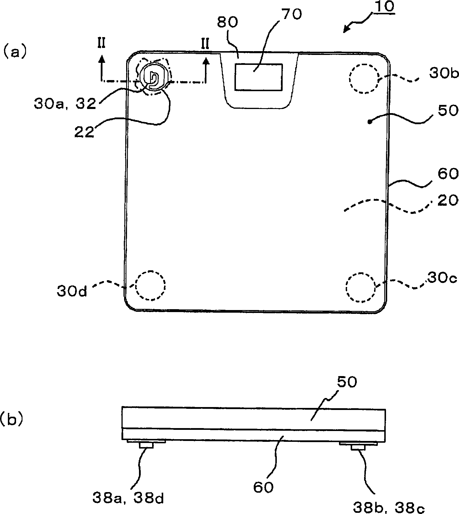
[0030] First, the outline of the electronic weighing scale 10 of this embodiment will be described.

[0031] The electronic weighing scale 10 includes a top plate member 20 on which an object to be measured (not shown) is placed on an upper surface, and a load cell unit 30 supporting the top plate member 20 from below, and at least a part of the load cell unit 30 is buried in the top plate member 20 installed in.

[0032] Next, the electronic weight scale 10 of this embodiment will be described in detail.

[0033] figure 1 (a) is a schematic plan view of the electronic weighing scale 10, figure 1 (b) is a front view of the electronic weighing scale 10 . but in figure 1 In (a), a part of the cover plate 50 is cut away to expose the mounting hole 22, and only the strain generator 32 in the load cell unit 30a provided in the upper left part of the figure is shown, and the cup member 40 is also omitted. icon.

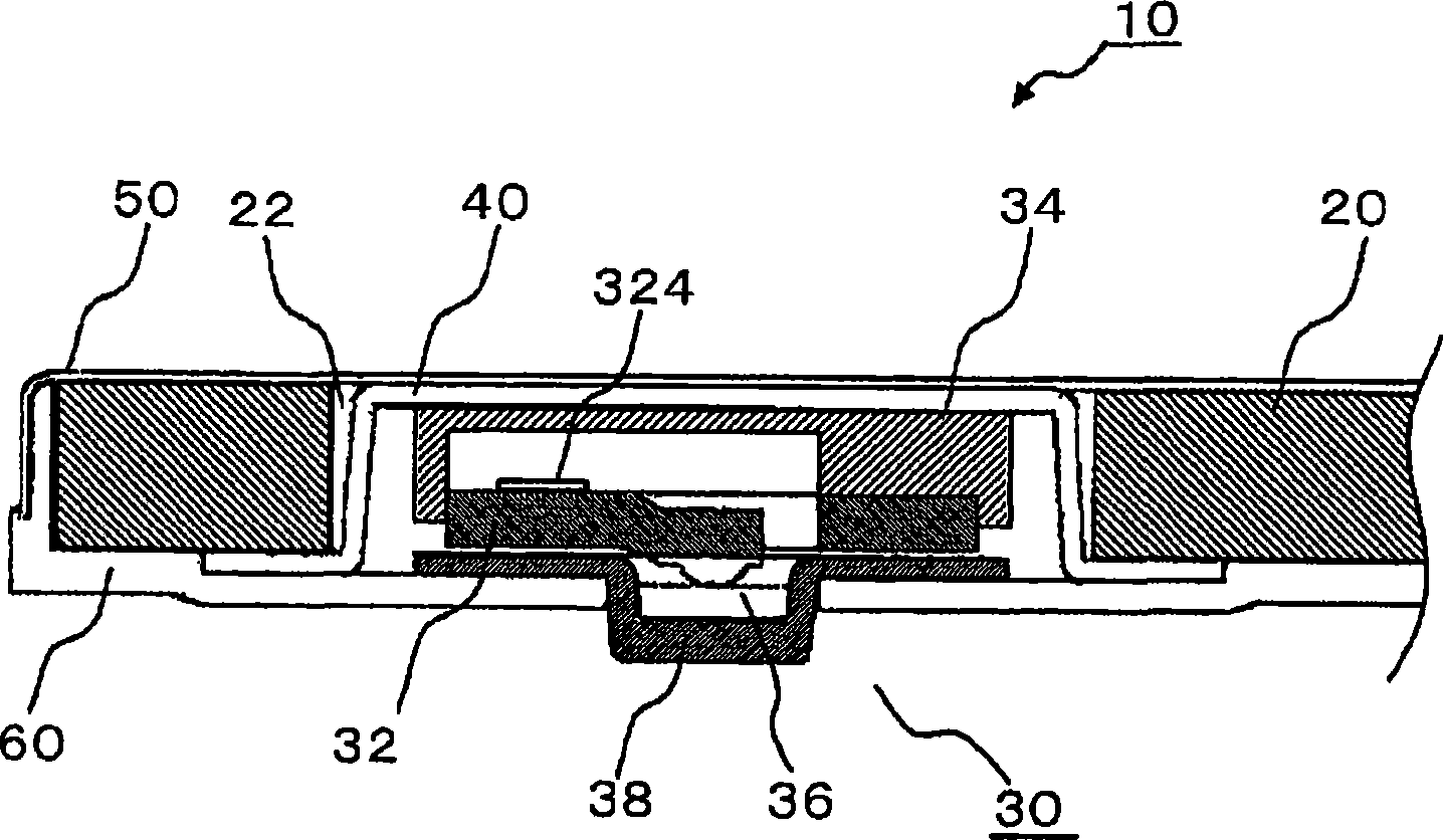
[0034] figure 2 is along figure 1 Section view of II-II i...


PUM


Abstract

The invention provides an electronic weighing scale possibly thinned overall characterized by comprising a top plate component (20) allowing on the top surface thereof placement of an object to be weighed; and load cell units (30) supporting the top plate component (20) from the lower side thereof, wherein the top plate component (20) is provided with mounting holes (22) so as to extend therethrough in the thickness-wise direction, allowing therein attachment of cup components (40) each having an opening (42) opened downward, and each load cell unit (30)is attached inside each cup component (40).

Description

technical field [0001] The present invention relates to an electronic weighing scale that uses a load cell unit to measure the mass of an object to be measured placed on the upper surface of a top plate member. Background technique [0002] In general electronic weight gauges, about four sets of load cell units are used to support the top plate member from below. The self-weight of the object to be measured placed on the top plate member is distributedly applied to the load cell unit. And, the mass of the object to be measured is measured by adding the measured values ​​on each load cell unit. [0003] A common structure of a load cell unit is that a plurality of strain gauges (strain gauges) are pasted on a sensing portion of a so-called strain generator (strain generator). As the strain generator, a diaphragm-type strain generator, a shear beam-type strain generator, and the like are known. These strain generators have in common that when a load is applied, a strain cor...

Claims


Application Information

Patent Timeline
Patent Type & Authority Applications(China)
IPC IPC(8): G01G19/44G01G3/12
CPCG01G21/23G01G23/3728G01G19/44G01G3/1402G01G21/28
Inventor 大迫直志井上和磨
Owner TANITA CORP
Why Eureka
Try Eureka