Gas amount measurement device

一种测量装置、气体量的技术,应用在分析材料、仪器等方向,能够解决不能测量等问题,达到准确性质的效果

Inactive Publication Date: 2009-07-22
NIPPON KINZOKU KAGAKU
View PDF0 Cites 2 Cited by
  • Summary
  • Abstract
  • Description
  • Claims
  • Application Information

AI Technical Summary

Problems solved by technology

[0005] However, the measuring device using the technology disclosed in Japanese Patent Laid-Open No. 2003-83865 can only measure the total amount of all gases present, and cannot measure the amount of each gas

Method used


Image

  • Gas amount measurement device
  • Gas amount measurement device
  • Gas amount measurement device

Examples


no. 1 approach

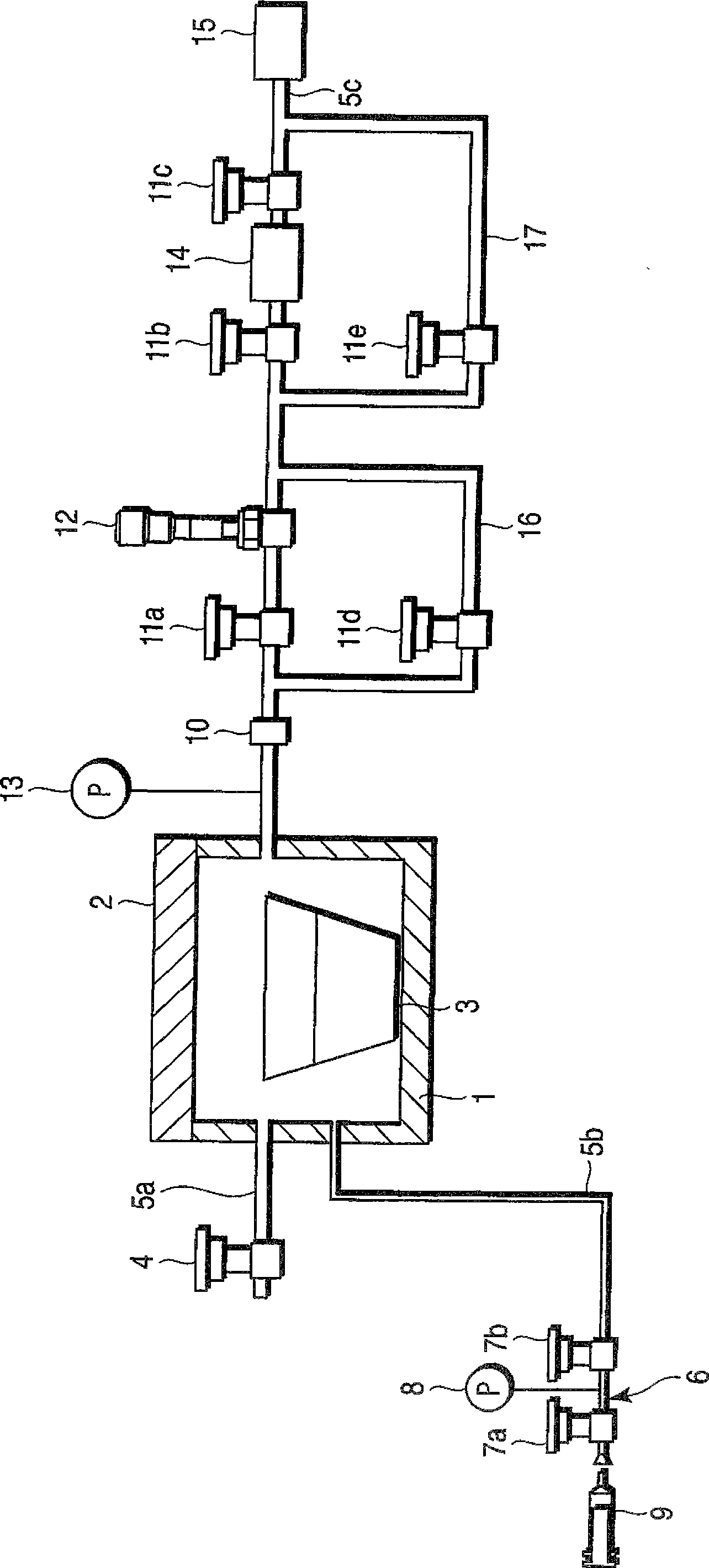
[0022] refer to figure 1 , reference numeral 1 denotes a vacuum container having a lid 2 that is freely openable / closeable. A sampling measuring cup 3 containing molten metal (not shown) serving as a sample is placed in the vacuum container 1 . The first pipe 5 a to which the purge valve 4 is connected is connected to the upstream side of the vacuum container 1 . The second pipe 5b to which the calibration gas generator 6 is connected is connected to the upstream side of the vacuum container. The calibration gas generator 6 is provided to include calibration valves 7a and 7b, a pressure gauge 8 connected to a pipe 5b between the valves 7a and 7b, and an air cylinder 9. When the calibration gas flows in, the internal pressure of the pipe 5b (pipe portion) between the valves 7a and 7b of the calibration gas generator 6 is adjusted to 1 atm.

[0023] The third pipe 5c is connected to the downstream side of the vacuum container 1 . From the side of the vacuum container 1, a va...

no. 2 approach

[0036] refer to Figure 4 , the gas amount measuring device according to the second embodiment will be described. Figure 4 neutralize figure 1 The same components as shown in are denoted by the same reference numerals and will not be described here again. and figure 1 Compared to the first embodiment shown, the second embodiment is characterized in that a heater 21 is provided around the sampling cup 3 .

[0037] According to the second embodiment, the drop in temperature of the molten metal contained in the sampling measuring cup 3 can be suppressed due to the presence of the heater 21 .


PUM


Abstract

A gas amount measuring device includes a vacuum container (1) filled with a molten metal, a first pipe (5a) being attached to the vacuum container (1), an air release valve (4) being attached to the first pipe (5a), a second pipe (5b) being attached to the vacuum container (1), a calibration gas generator (6) being attached to the second pipe (5b), a third pipe (5c) being attached to the vacuum container (1), a vacuum gauge (13), a first valve (11a), a leak valve (12), a second valve (11b), a turbomolecular pump (14), a third valve (11c), and a roughing pump (15) being attached to the third pipe (5c) in order from a vacuum container (1) side, a first bypass pipe (16) connecting the third pipe (5c) between the vacuum container (1) and the first valve (11a) to the third pipe (5c) between the leak valve (12) and the second valve (11b), a fourth valve (11d) being attached to the first bypass pipe (16), and a second bypass pipe (17) connecting the third pipe (5c) between the leak valve (12) and the second valve (11b) to the third pipe (5c) between the third valve (11c) and the roughing pump (15), a fifth valve (11e) being attached to the second bypass pipe (17).

Description

technical field [0001] The invention relates to a gas quantity measuring device. More specifically, the present invention relates to a gas amount measuring device for measuring the total amount of gas contained in molten metal or the amount of gas adsorbed in inclusions. Background technique [0002] Specific metals or alloys are often employed as components in, for example, automotive engines. At the same time, it is generally known that the impurity gas content per unit weight of the component after refining is lower than that before refining. This is due to the vaporization of impurity gases contained in the sample, ie the component, during the refining process. In this case, the refined components are melted again in order to reduce the impurity gas content in the components as much as possible. However, re-melting the refined components can undesirably result in a cost spike. [0003] In addition, from the viewpoint of efficient use of resources, recycling of used m...

Claims


Application Information

Patent Timeline
Patent Type & Authority Applications(China)
IPC IPC(8): G01N7/14
CPCG01N7/14
Inventor 阿部哲也秦野岁久平塚一长谷川浩一田岛保英大间知聪一郎
Owner NIPPON KINZOKU KAGAKU
Why Eureka
Try Eureka