Light source module, surface area light-emitting unit, and surface area light-emitting device

A light source module and a surface-emitting technology, which is applied to semiconductor devices, light sources, electric light sources, etc. of light-emitting elements, can solve problems such as uneven brightness and uneven color of LED components, achieve suppression of uneven light emission and color, and simplify installation operation, and the effect of reducing manufacturing costs

Inactive Publication Date: 2009-07-22
KOHA
View PDF4 Cites 12 Cited by
  • Summary
  • Abstract
  • Description
  • Claims
  • Application Information

AI Technical Summary

Problems solved by technology

[0004] In addition, although the brightness of an LED depends on the light-emitting characteristics of the single LED ele

Method used


Image

  • Light source module, surface area light-emitting unit, and surface area light-emitting device
  • Light source module, surface area light-emitting unit, and surface area light-emitting device
  • Light source module, surface area light-emitting unit, and surface area light-emitting device

Examples


Example

[0039] [First Embodiment]

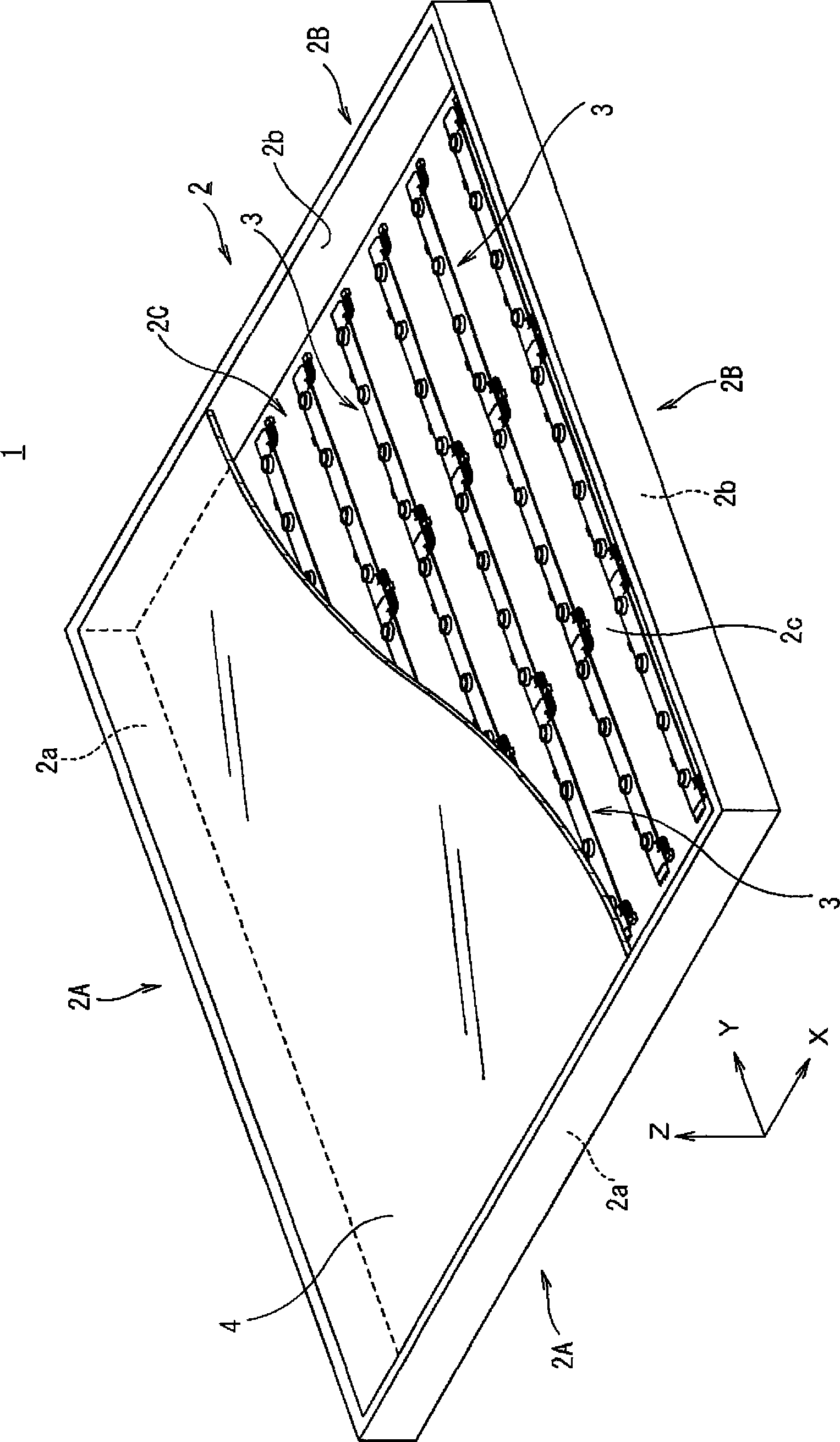
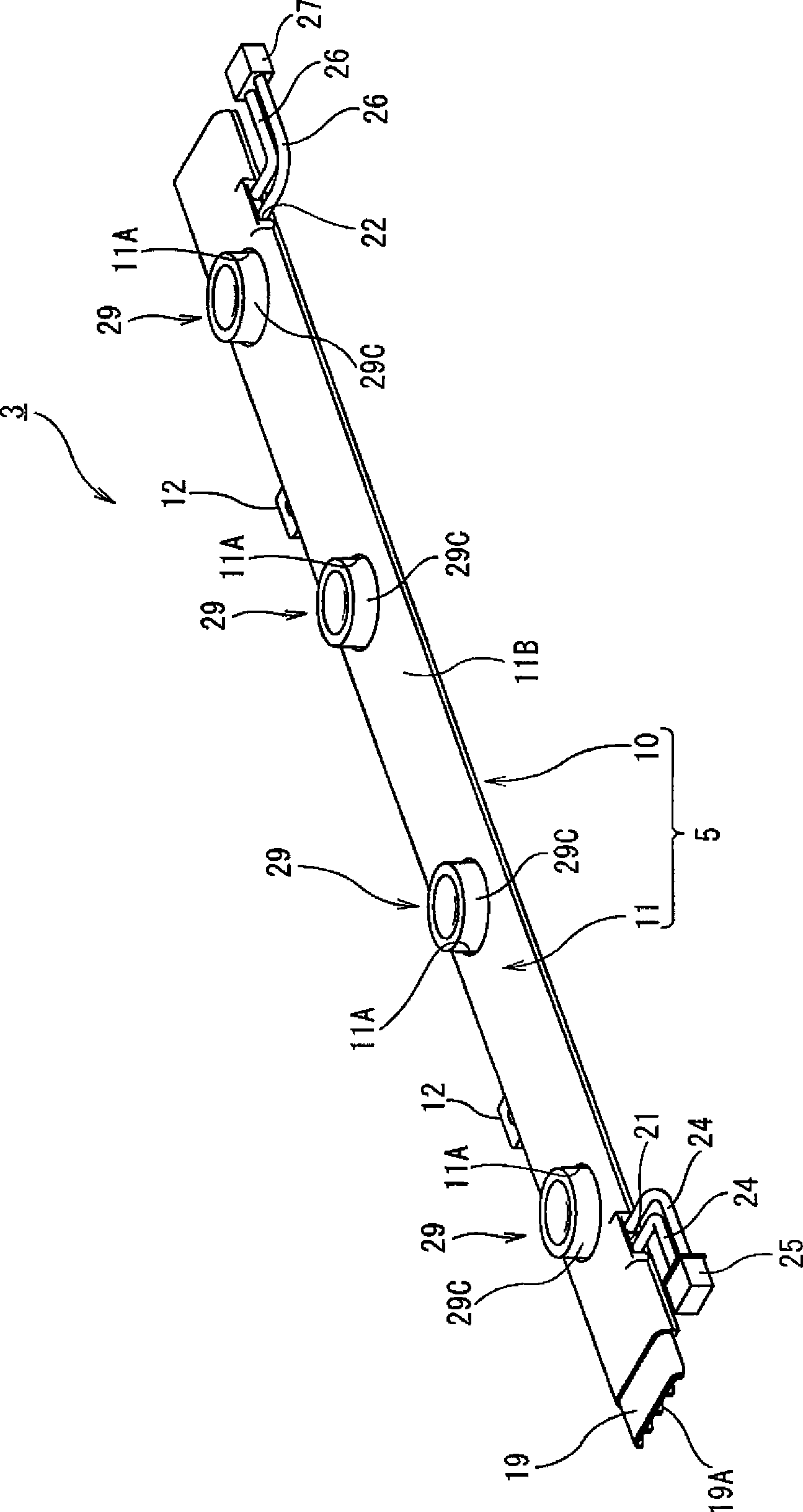
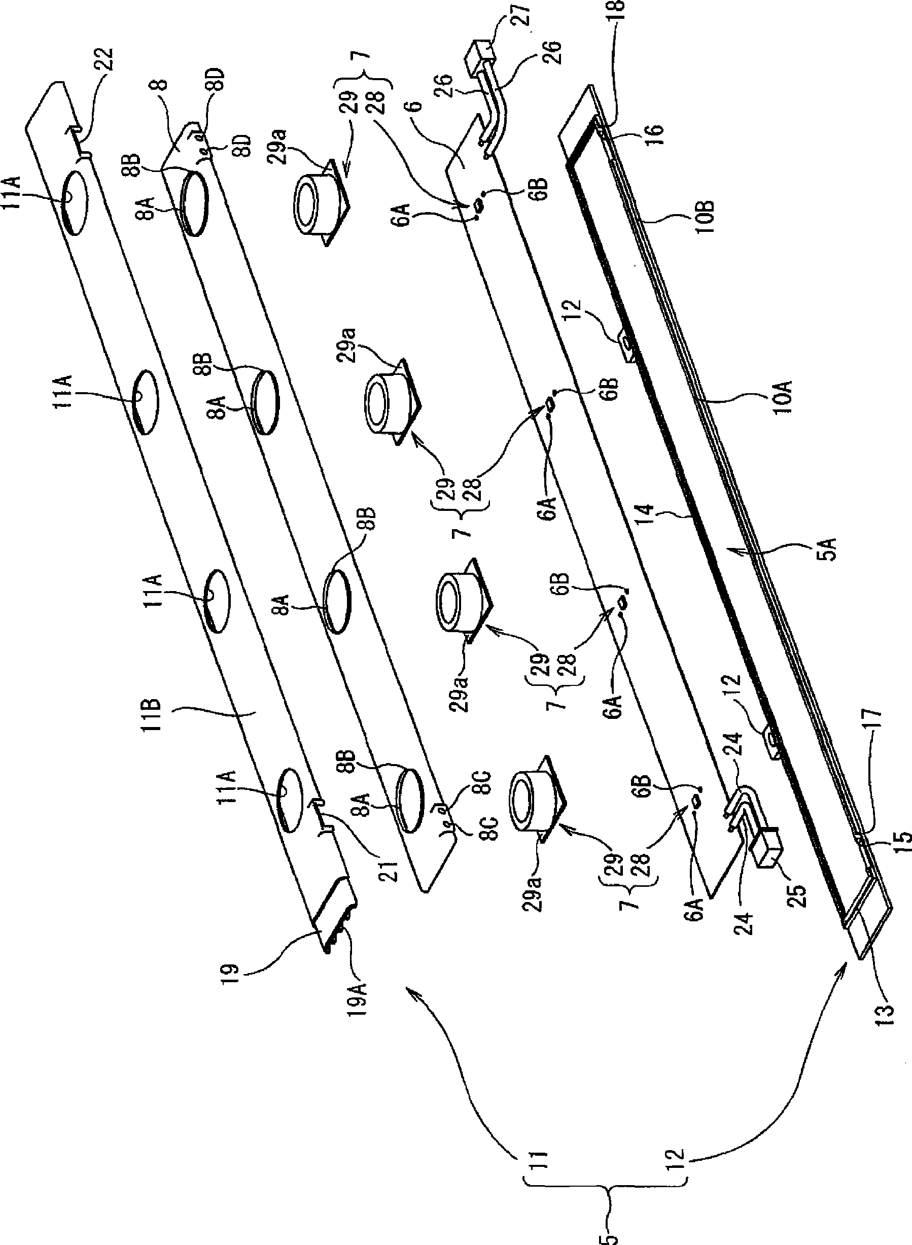
[0040] figure 1It is a perspective view which shows the whole surface light emitting device provided with the surface light emitting module of 1st Embodiment of this invention. figure 2 It is an assembled perspective view showing the entire surface light emitting module according to the first embodiment of the present invention. image 3 It is an exploded perspective view showing the entire surface light emitting module according to the first embodiment of the present invention. Figure 4 It is a perspective view showing the connection state of the surface light emitting module according to the first embodiment of the present invention. Figure 5 It is a perspective view which shows the state which released the connection of the surface light emitting module concerning 1st Embodiment of this invention. Image 6 It is a perspective view which shows the state which looked at the connection part of the surface light emitting module of 1st Embodimen...

Example

[0091] [Second Embodiment]

[0092] Figure 14 It is an assembled perspective view showing the entire surface light emitting module according to the second embodiment of the present invention. Figure 15 It is a cross-sectional view shown for explaining the light-emitting lamp of the surface light-emitting module according to the second embodiment of the present invention. Figure 15 (a) means Figure 14 A-A sectional view, Figure 15 (b) means Figure 14 B-B sectional view. Figure 16 It is a figure which shows the light direction conversion part in the light emitting lamp of the surface light emitting module concerning 2nd Embodiment of this invention. Figure 16 (a) represents a perspective view, Figure 16 (b) represents a top view, Figure 16 (c) represents a bottom view. Figure 17 This is a cross-sectional view showing the light-direction converting portion in the light-emitting lamp of the surface-emitting module according to the second embodiment of the presen...

Example Embodiment

[0101] [Third Embodiment 1

[0102] Figure 18 This is a cross-sectional view showing the light direction converting portion in the light-emitting lamp of the surface-emitting module according to the third embodiment of the present invention. In the optical element for light direction conversion of the third embodiment, in the optical element 29 for light direction conversion of the first embodiment, an inclined light reflection surface is provided between the upper light reflection surface 29B and the side light exit surface 29C 29D.

[0103] The light emitted from the LED 28 and the light incident from the second light incident surface 29c on the bottom surface of the optical element 29 for light direction conversion are reflected by the light reflecting surface 29B on the upper surface and almost emitted from the light emitting surface 29C on the side surface. Between the reflection surface 29B and the light exit surface 29C, a light reflection surface 29D having a shape ...


PUM


Abstract

The invention provides a light source module, surface area light-emitting unit, and surface area light-emitting device that have versatility, where installation work is simplified and production costs are reduced, and where irregularity of light emission and color is sufficiently suppressed. The light source module has a light direction-converting optical element (29) and an LED (28). The light direction-converting optical element (29) has a recess (290) with a light incident surface (29A) into which light enters, a light reflecting surface (29B) for reflecting light entered from the light incident surface (29A), and a light emitting surface (29C) for emitting to a side the light reflected by the light reflecting surface (29B). The LED (28) is placed in a recess (290) of the light direction-converting optical element (29) with a gap provided in between them and applies light to the light incident surface (29A).

Description

technical field [0001] The present invention relates to a light source module, a surface emitting module, and a surface emitting device, and more particularly, to a light source module, a surface emitting module, and a surface emitting device using a light emitting diode (Light Emitting Diode: LED) as a light emitting part. Background technique [0002] As is well known, fluorescent lamps are generally used as light sources in surface light-emitting devices used for displaying images, signboards, etc., and for store lighting. However, since fluorescent lamps use harmful mercury, there is a problem that proper disposal of industrial waste is required. In addition, fluorescent lamps have a short lifespan and high running costs. [0003] In recent years, technology using LEDs has been proposed as a light-emitting lamp of a surface light-emitting device that solves such a problem. Since LEDs are manufactured based on semiconductor manufacturing technology, they have excellent ...

Claims


Application Information

Patent Timeline
IPC IPC(8): F21S2/00F21V7/10G09F13/04H01L33/00F21Y101/02H01L33/58H01L33/60
CPCH01L2924/0002H01L33/60G02B17/0872H01L33/58G02F2001/133612G02B19/0028G02F1/133603H01L25/0753G02B19/0071G02B19/0066F21V5/046F21Y2103/10F21Y2115/10G02F1/133612H01L2924/00
Inventor 吉川幸雄青木和夫河又正敏西川明宏山田朋宏中台太郎
Owner KOHA
Why Eureka
Try Eureka