
A tool holder

A tool, surgical tool technology, applied in the field of surgical systems, which can solve the problems of movement, undesired tools, occupying the operating room, etc.

Inactive Publication Date: 2009-07-29
PROSURGICS
View PDF0 Cites 2 Cited by
  • Summary
  • Abstract
  • Description
  • Claims
  • Application Information

AI Technical Summary

Problems solved by technology

[0004] However, this method has disadvantages: the assistant doctor may need to keep the tool in the exact same position for several hours; Miscommunication causing undesired movement of the tool, or the physician assistant may not be occupying valuable space in the operating room as desired

Method used


Image

  • A tool holder
  • A tool holder
  • A tool holder

Examples


Embodiment Construction

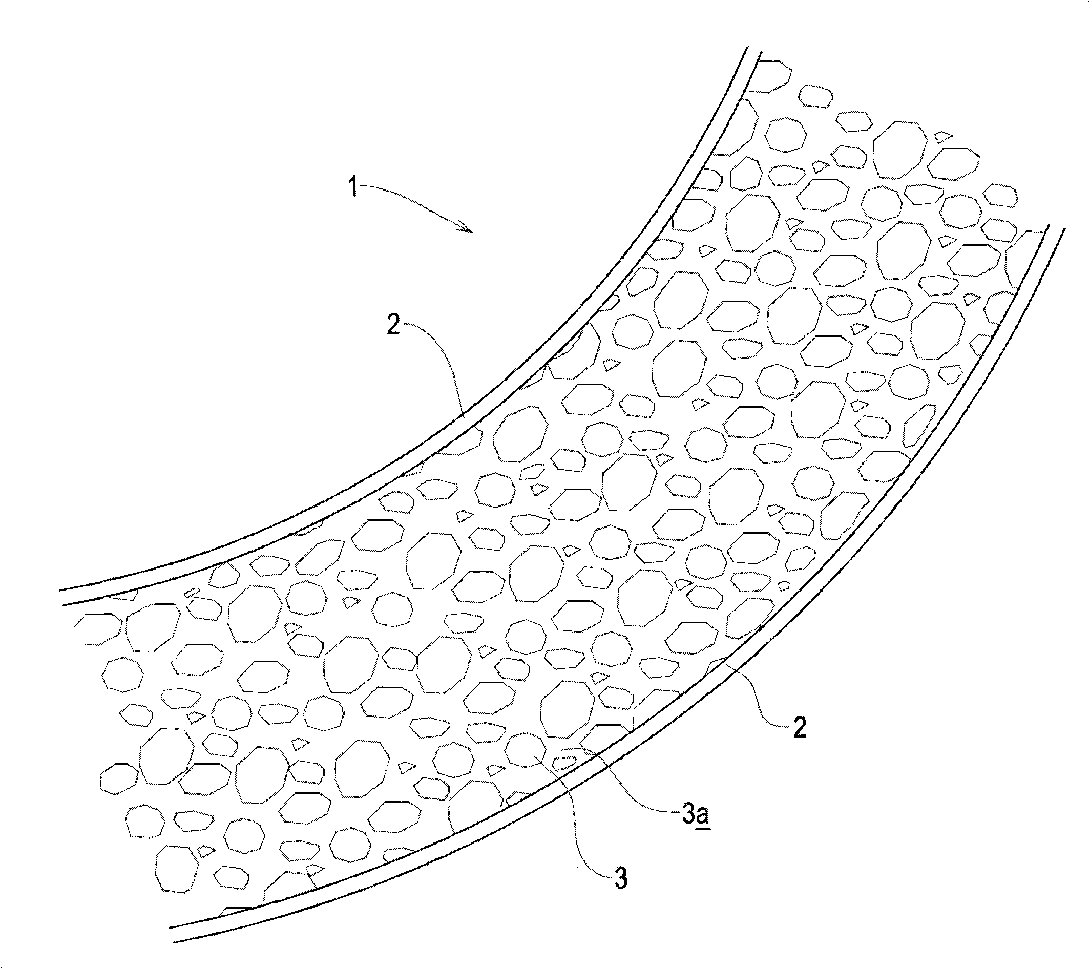
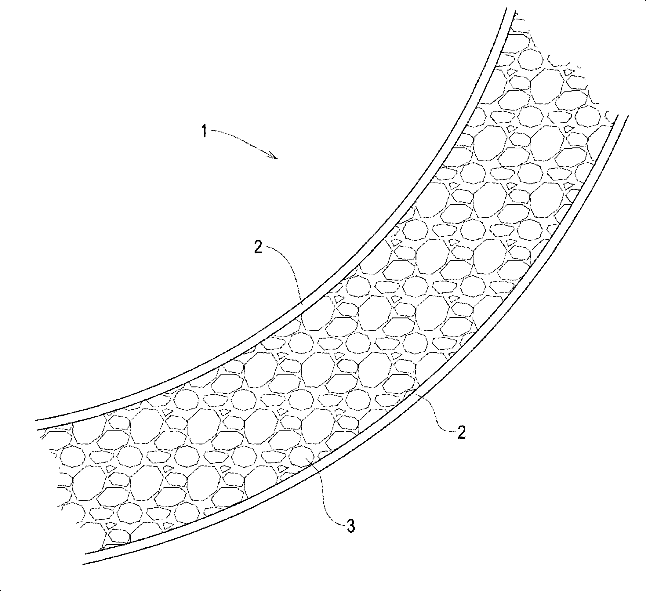
[0038] The arm 1 of the surgical tool supporting device according to an embodiment of the present invention comprises a tubular elongate body having an outer wall 2 defining a lumen 3a (see figure 1 with 2 ).

[0039] The tubular elongate body of the arm 1 may have a circular cross-section or may have a differently shaped cross-section (eg triangular or hexagonal).

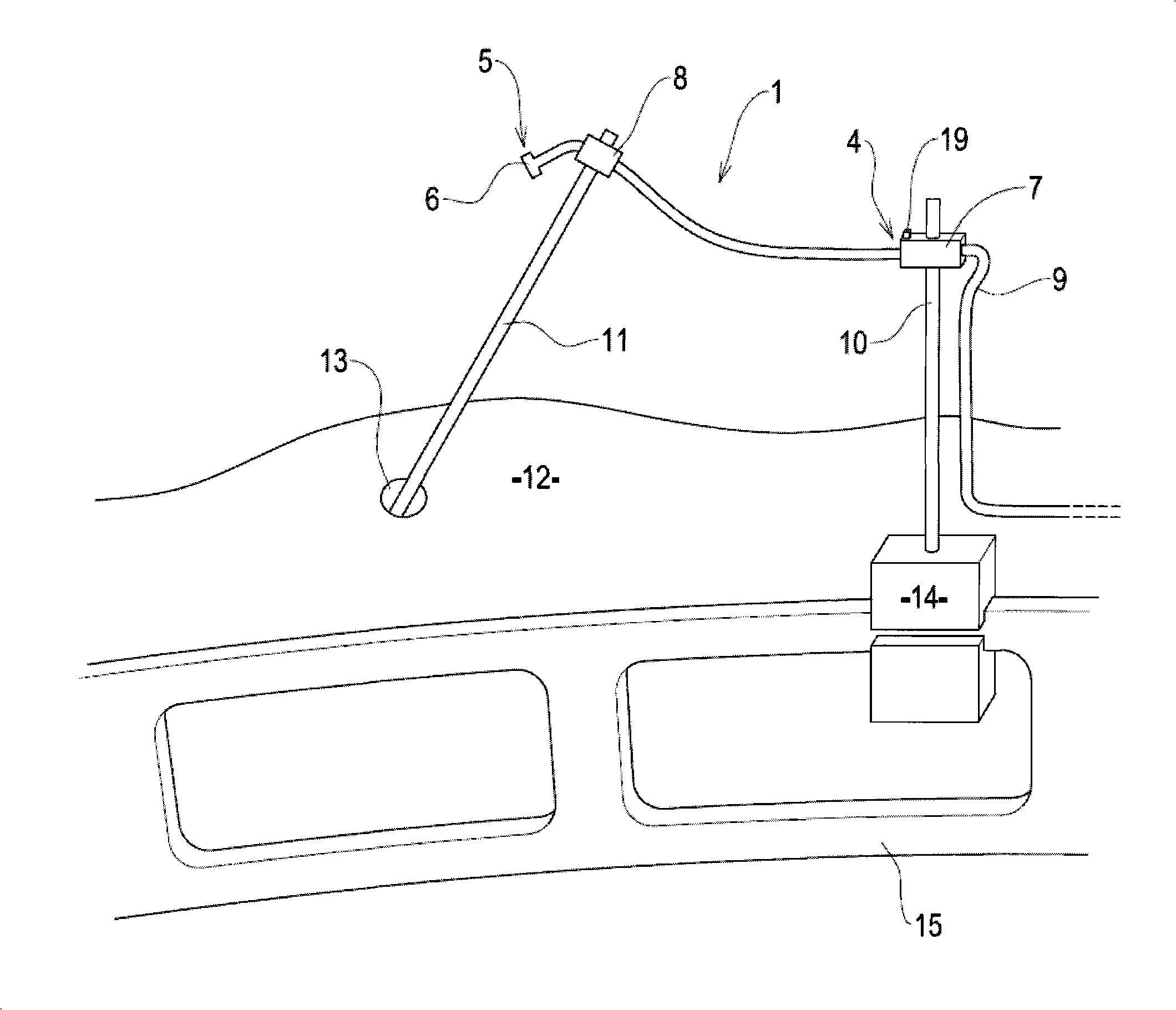
[0040] The distal end 5 of the arm 1 (see image 3 with 4 ) is basically sealed. This can be done by using plug6 (eg image 3 shown) to complete. Said bung 6 may be a separate part inserted into the lumen 3a of the tubular elongate body of said arm 1 at the distal end 5 of said arm 1 . The stopper 6 may have a friction fitting, may be adhered to the outer wall 2 of the arm 1 , or may be integrated with the outer wall 2 .

[0041] Alternatively, the distal end 5 of the arm 1 is substantially sealed by adhering together opposing parts of the outer wall 2 of the arm 1 . This can be achieved by melting or part...


PUM


Abstract

A surgical tool support device includes an arm. The arm includes a flexible tubular main body; and a plurality of beads contained within the tubular main body. In a first configuration, a fluid at least partially surrounds the plurality of beads. In a second configuration, at least some of the fluid is evacuated such that the rigidity of the arm is increased.

Description

technical field [0001] The present invention relates to a surgical tool support, a method of manufacturing a surgical tool support, a valve module coupled to a surgical tool support, a support arm and a surgical system. Background technique [0002] Endoscopic surgery is known. It is also known to provide a robot configured to hold and manipulate an endoscope during endoscopic surgery. [0003] During such surgical operations it is often necessary to hold the tool in a completely fixed position. For example, such tools may include retractors that are inserted through an incision in a patient and used to hold a portion of the patient's internal organs away from the area of ​​the surgical object. An example of such use of a retractor in this manner is traction of liver lobes during bariatric surgery. This role is typically performed by a physician assistant who holds the tool and makes any minor adjustments to the tool's position in order to assist the physician. [0004] ...

Claims


Application Information

Patent Timeline
Patent Type & Authority Applications(China)
IPC IPC(8): A61B1/00A61B17/94A61B19/00
CPCA61B2017/00561A61B2017/0023A61B2019/266A61B2017/00566A61B17/02A61B19/2203A61B19/5212A61B2017/00535A61B19/26A61B90/361A61B90/50A61B34/30A61B2090/508
Inventor 帕特里克·阿姆斯特朗·芬利
Owner PROSURGICS
Learn More