
Verifying apparatus for measuring extra-high voltage transformer error

A technology for voltage transformer and error measurement, applied in measurement devices, measurement of electrical variables, instruments, etc., can solve problems such as increased uncertainty, measurement failure, and higher requirements for measurement personnel, to avoid nonlinearity and easy saturation, Improve convenience and reliability, improve the effect of allowing input current

Active Publication Date: 2012-03-14
STATE GRID ELECTRIC POWER RES INST +3
View PDF0 Cites 0 Cited by
  • Summary
  • Abstract
  • Description
  • Claims
  • Application Information

AI Technical Summary

Problems solved by technology

But this method has the following disadvantages: 1. The measured reading is the capacitance ratio C X / C N And the dielectric loss tgδ, the ratio difference and phase difference of the transformer need to be converted mathematically, which is very inconvenient to use and has high requirements for the measuring personnel; 2. When measuring a 1000kV voltage transformer, the rated capacitance of the standard capacitor C N Generally, if 50pF is selected, the current of the input capacitor bridge QS is more than ten milliamps, which is greater than the maximum allowable input current of 10mA for the general comparator type high-voltage capacitor bridge QS, which may cause measurement failure or even damage the capacitor bridge QS; 3. Comparison Due to the use of electronic circuit conversion, the measurement error of the instrument-type high-voltage capacitor bridge QS is nonlinear, which increases the uncertainty of measurement; 4. The measurement circuit of the equal-power capacitor bridge belongs to the principle of direct comparison rather than difference measurement. , relatively poor anti-interference, not suitable for on-site measurement in harsh electromagnetic environment

Method used


Image

  • Verifying apparatus for measuring extra-high voltage transformer error
  • Verifying apparatus for measuring extra-high voltage transformer error
  • Verifying apparatus for measuring extra-high voltage transformer error

Examples


Embodiment Construction

[0014] The calibration device for error measurement of UHV voltage transformers according to the present invention will be further described below in conjunction with the accompanying drawings and embodiments.

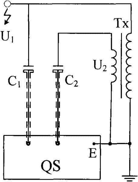
[0015] figure 1 Instructions marked in: Tx-potential transformer under test; U 1 - the primary side voltage of the voltage transformer under test; U 2 -Secondary side voltage of the voltage transformer under test; QS-capacitance bridge; E-housing ground; C 1 - High voltage standard capacitor; C 2 - Low voltage standard capacitors.

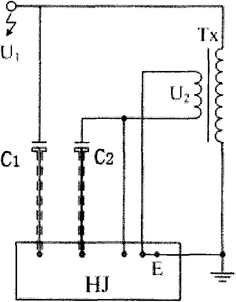
[0016] figure 2 Explanation of marks in: HJ—Example of the present invention.

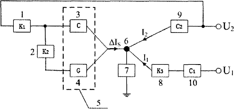
[0017] image 3 Instructions marked in: 1, 2-precision voltage divider; 3-standard capacitor box; 4-standard conductance box; 5-admittance network; 6-balance node; 7-zero indicator; 8-inductive shunt; 9-Low voltage standard capacitor (same as figure 1 Middle C 2 ); 10-high voltage standard capacitor (same as figure 1 Middle C 1 ); I 1 , I 2 - curre...


PUM


Abstract

The invention provides a calibration device used for error measurement of a super-high voltage transformer, comprising an admittance network consisting of a standard capacitance box and a standard conductive box, a precise voltage divider, an induction-typed shunt and a null instrument. The calibration device can be used as the error measurement device when the voltage transformer is being calibrated by the capacitance-typed voltage proportion standard, adopts the difference value measurement principle to calibrate the ratio difference and the phase difference of the voltage transformer to be tested, realizes directly reading the ratio difference and phase difference of the voltage transformer to be calibrated by the conductivity quantity and capacitance quantity of the admittance network, and can calibrate the electromagnetism-typed or capacitance-typed voltage transformer within the voltage range of 110-1000KV. When calibrating the voltage transformer used for the measurement with the accuracy class of 0.05 or above, the uncertainty introduced by the calibration device is less than or equal to 5.3*10<-6> and when calibrating the voltage transformer used for the power with the accuracy class of 0.05 or above, the uncertainty introduced by the calibration device is less than or equal to 2.3*10<-5>.

Description

technical field [0001] The invention relates to a voltage transformer error calibration device, in particular to a calibration device for measuring the error of an ultra-high voltage (1000kV and above voltage level) voltage transformer. Background technique [0002] With the construction of ultra-high voltage and ultra-high voltage power grids and the continuous progress of ultra-high voltage technology, in the research of high voltage technology, the test and research of high voltage and high current equipment, gateway measurement, technical level evaluation of power transmission and transformation equipment, line parameter measurement, etc. All aspects require accurate measurement of voltage values, so the need to carry out 1000kV UHV value traceability and value transmission is particularly urgent. Since our country has not established (Single-phase rated voltage in UHV power grid) power frequency voltage ratio standard. At present, the error calibration of UHV voltage ...

Claims


Application Information

Patent Timeline
Patent Type & Authority Patents(China)
IPC IPC(8): G01R35/00
Inventor 王乐仁雷民章述汉周峰郑汉军
Owner STATE GRID ELECTRIC POWER RES INST
Learn More