Supercharge Your Innovation With Domain-Expert AI Agents!

High efficiency zero voltage, zero current whole bridge converter

A full-bridge converter, zero-current technology, applied in the field of zero-current full-bridge converters and zero-voltage, can solve the problems of large difference in duty ratio between primary and secondary sides, large loss of external auxiliary components, and output load influence, etc. Good EMO performance, small switching noise, simple drive effect

Active Publication Date: 2011-05-18
XUJI GRP +2
View PDF0 Cites 0 Cited by
  • Summary
  • Abstract
  • Description
  • Claims
  • Application Information

AI Technical Summary

Problems solved by technology

The disadvantage of this circuit is: when the primary side switch tube is turned on, the secondary side needs to provide the clamping capacitor C b1 Charging, resulting in a large transient current spike in the primary switch tube; the clamping capacitor C b1 When clamped, the current in the output inductor Lf is controlled by C b1 provided, does not feed back to the primary, resulting in a super-forearm Q 1 , Q 3 loss of zero voltage switching condition
[0003] There are various types of zero-voltage and zero-current full-bridge circuits, which have disadvantages: large loss and low efficiency of external auxiliary components; complex control of auxiliary components; large difference in duty ratio between the primary and secondary sides makes it difficult to calculate the turn ratio of the transformer ;The range of realizing zero voltage and zero current is limited, which is affected by input voltage and output load

Method used


Image

  • High efficiency zero voltage, zero current whole bridge converter
  • High efficiency zero voltage, zero current whole bridge converter
  • High efficiency zero voltage, zero current whole bridge converter

Examples


Embodiment Construction

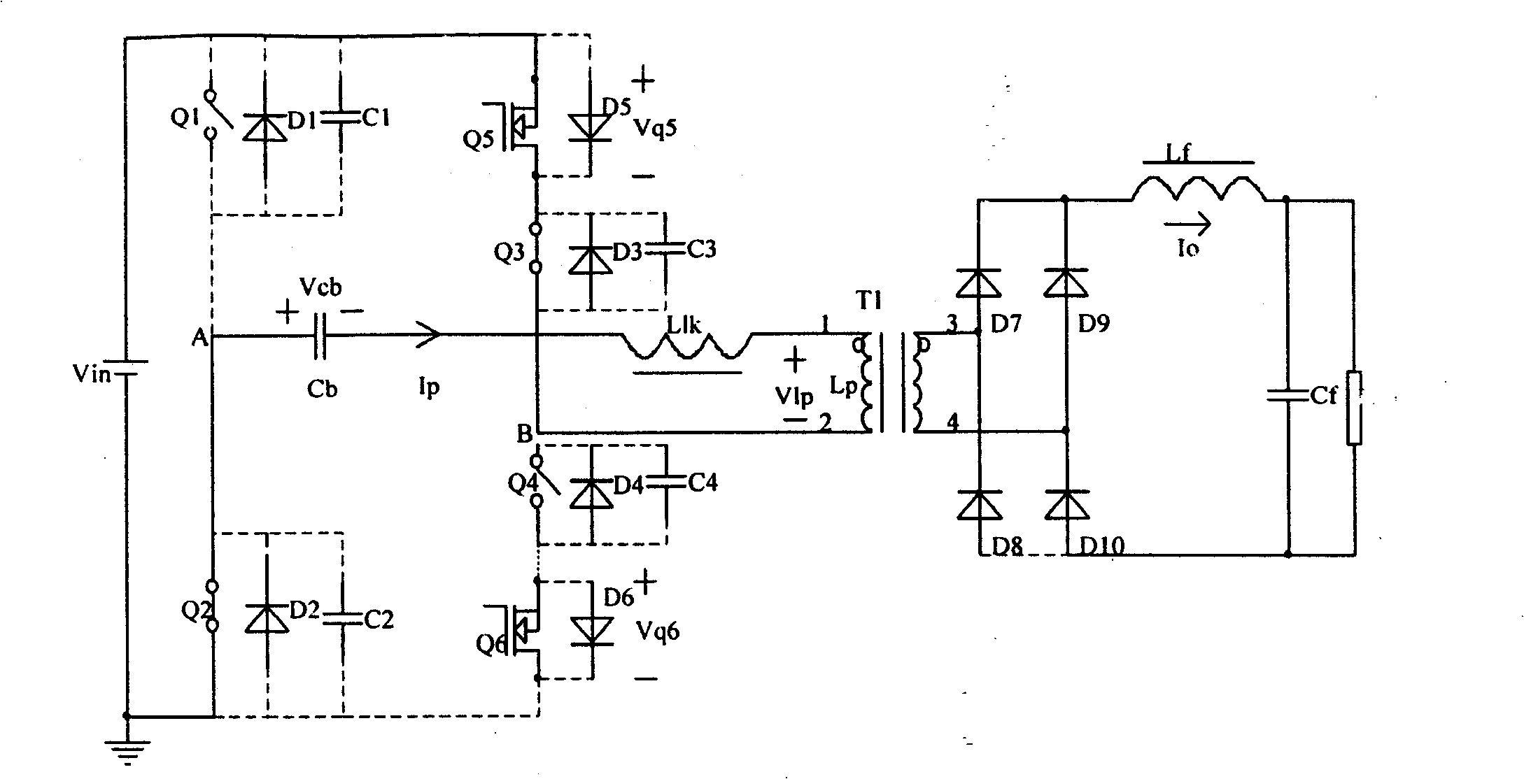
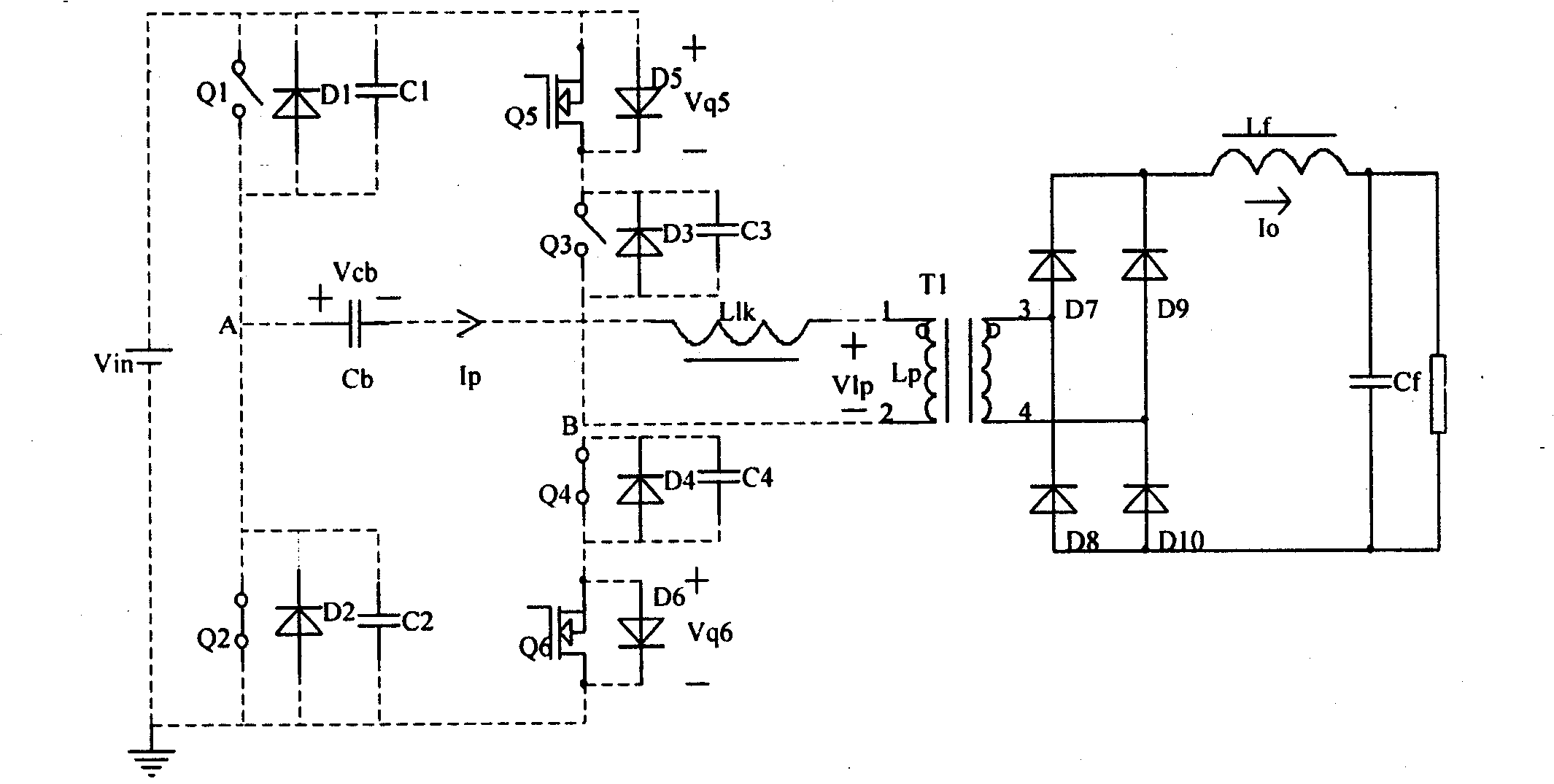
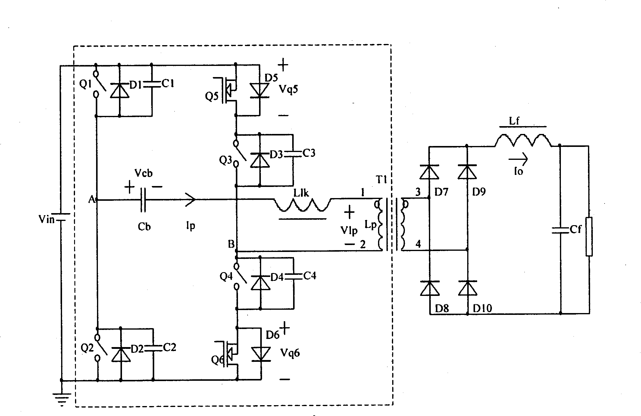
[0025] Converter of the present invention is made up of following several parts, with reference to Figure 4 Shown in the dotted box:

[0026] 1. Basic full-bridge circuit: It consists of four switching tubes Q1, Q2, Q3, Q4 and transformer T1. Q1, Q2, Q3, and Q4 can be MOS tubes or IGBTs; among them, Q1, Q2 are the leading bridge arms of the full-bridge circuit, and Q3, Q4 are the lagging bridge arms of the full-bridge circuit; D1, D2, D3, and D4 are respectively are the body diodes or external parallel diodes of Q1, Q2, Q3, and Q4; C1, C2, C3, and C4 are the parasitic capacitances or external parallel capacitances of Q1, Q2, Q3, and Q4, respectively; L lk It is the leakage inductance of the primary side of the transformer T1.

[0027] 2. DC blocking capacitor C b , connected in series to the primary side of the transformer T1. After the super forearm Q1 (or Q2) is turned off, the DC blocking capacitor C b The voltage on can make the transformer T1 primary current I p ba...


PUM


Abstract

The invention relates to a high-efficiency full bridge converter with zero voltage and zero current, consisting of the following parts: (1) a basic full bridge converter consisting of four switching tubes Q1, Q2, Q3 and Q4 and a transformer T1, wherein, the Q1 and the Q2 are leading bridges of the full bridge converter, and the Q3 and the Q4 are lag bridges of the full bridge converter; and Llk is a primary side leakage inductor of the transformer T1; (2) a stopping condenser Cb connected in series with the primary side of the transformer T1, when the leading bridge Q1 (or Q2) is shut off, the voltage of the stopping condenser Cb can lead the current Ip at the primary side of the transformer T1 to return to zero; and (3) MOS tubes Q5 and Q6 with low voltage and low conducting internal resistance, wherein, the Q5 is connected in series with the lag bridge Q3; the Q5 and the Q2 are opened synchronously; the shut-off of the Q5 is synchronous with the opening of Q1; Q6 is connected in series with the lag bridge Q4; the drive of the Q6 is complemented with the Q5; the Q6 and the Q1 are opened synchronously, and the shut-off of the Q6 is synchronous with the opening of the Q2.

Description

technical field [0001] The invention relates to a high-efficiency zero-voltage, zero-current full-bridge converter, belonging to a power switching power supply. Background technique [0002] Nowadays, switching power supplies are widely used in various industries and fields, and users have put forward more and more stringent requirements for switching power supplies: high power density, high reliability, high efficiency, and good electromagnetic compatibility performance. In high-power switching power supplies, full-bridge circuits are most widely used. In order to meet the above requirements of users, many zero-voltage (ZVS), zero-current (ZCS) soft-switching full-bridge circuit topologies have emerged. To sum up, there are the following: 1. The simplest method is to connect the saturated inductance in series with the primary side of the basic full-bridge circuit transformer, and use the characteristic of infinite reverse impedance after the saturated inductance is saturat...

Claims


Application Information

Patent Timeline
Patent Type & Authority Patents(China)
IPC IPC(8): H02M3/28
Inventor 李彩生
Owner XUJI GRP
Features
  • R&D
  • Intellectual Property
  • Life Sciences
  • Materials
  • Tech Scout
  • Unparalleled Data Quality
  • Higher Quality Content
  • 60% Fewer Hallucinations
Learn More