

Image capturing module, method for manufacturing the image capturing module, and electronic information device
An image capture and imaging technology, applied in image communication, radiation control devices, semiconductor/solid-state device manufacturing, etc., can solve problems such as weakening
- Summary
- Abstract
- Description
- Claims
- Application Information
AI Technical Summary
Problems solved by technology
Method used
Image

Examples
Embodiment 1
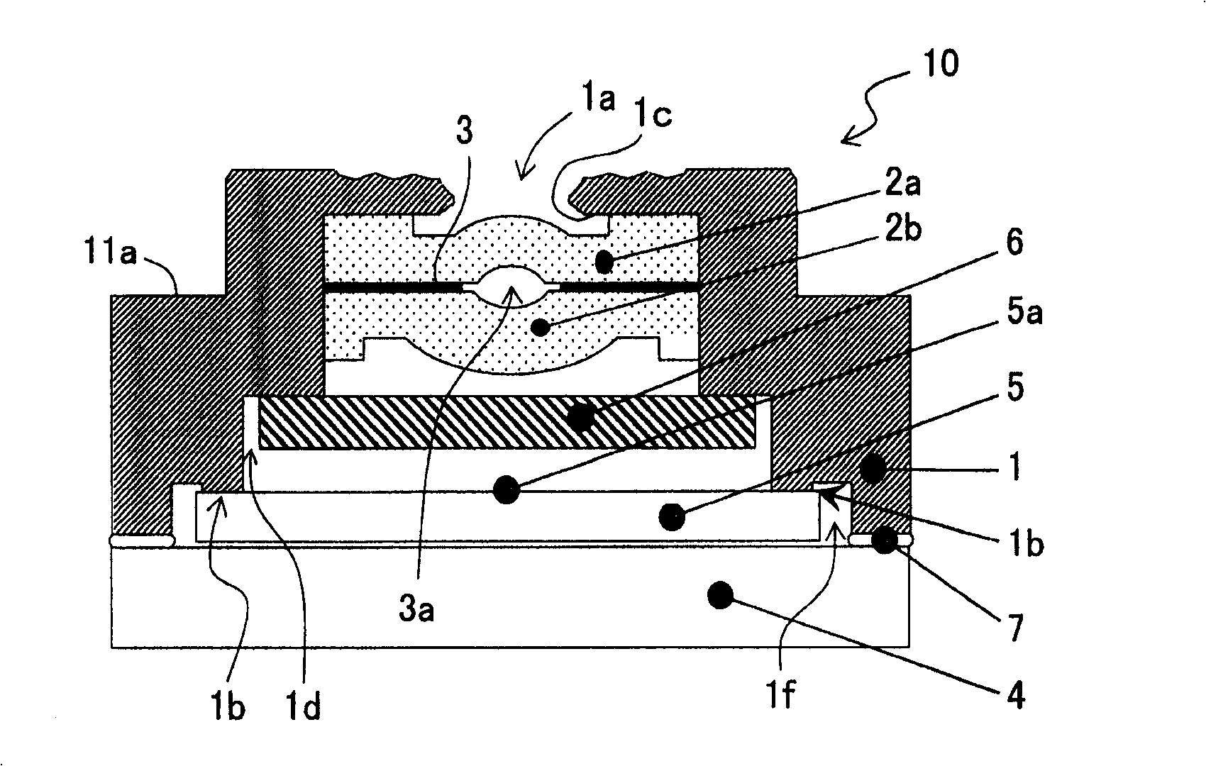
[0108] figure 1 is a longitudinal cross-sectional view of the basic structure of the image capture module in Embodiment 1 of the present invention.
[0109] exist figure 1 Among them, the image capture module 10 according to Embodiment 1 of the present invention includes: a holder member 1 as a dustproof box; a first focusing lens 2a and a second focusing lens 2b, which are vertically accommodated in the holder member 1; A light-shielding film 3 between the first focusing lens 2a and the second focusing lens 2b, a substrate 4; a sensor chip 5 provided on the substrate 4 as a solid-state image capturing chip; an infrared (IR) cut filter 6 , which is fixed on the first step portion 1d in the holder member 1, and is positioned across between the second focusing lens 2b and the sensor chip 5; and an adhesive portion 7, which is used to hold the holder member 1 The bottom surface of the outer sidewall and the substrate 4 are bonded.
[0110] The structure of the dustproof hold...
Embodiment 2
[0125] In Embodiment 1 as described above, a cartridge is described in which the height-direction position determining portion 1b of the holder member 1 with a flat surface is placed directly on the upper surface of the sensor chip 5 to accurately determine the position determination portion 1b fixed on the support. The distance between the lens of the sensor member 1 and the upper surface of the sensor chip 5 . In Embodiment 2, a case will be described in which the height-direction position determining portion 1b disposed on the upper surface of the sensor chip 5 has a pointed shape (circular or elliptical) instead of a flat surface shape.
[0126] Figure 4 is a longitudinal cross-sectional view of the basic structure of the image capture module in Embodiment 2 of the present invention.
[0127] exist Figure 4 Among them, the image capture module 10A according to Embodiment 1 of the present invention includes: a holder member 1A used as a dustproof box; a first focusing l...
Embodiment 3
[0132] In Embodiment 2 described above, the height-direction position determining portion (protruding portion) in a pointed shape (circular shape or elliptical shape) was described. In Embodiment 3, the number of point-shaped height-direction position determining portions will be described.
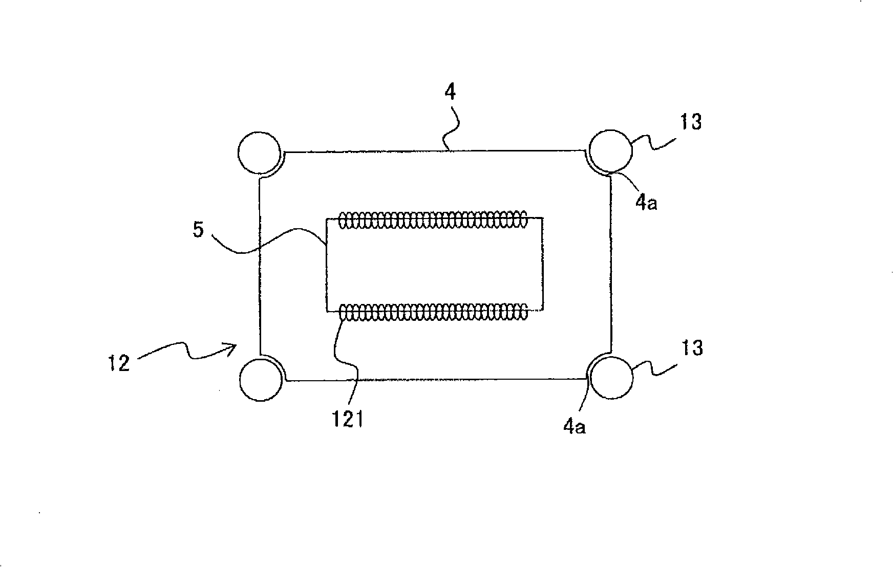
[0133] 5 is a plan view showing the positional relationship between the upper surface of the sensor chip and the height-direction position determining portion in the image capturing module according to the third embodiment of the present invention. Note that the continuation Figure 1-4 The reference signs in , the same reference signs represent parts with the same function or effect.
[0134]In FIG. 5 , the positional relationship between the upper surface of the sensor chip 5 and the three tips of the height-direction position determining portion is formed so that the three tips are positioned away from the image capturing area 5 a. The three tips of the position determining portion i...
PUM
 Abstract
Description
Claims
Application Information