A method and apparatus for joining metals using self piercing rivets with preheating
A technology of equipment and components, which is applied in the field of connecting metal and equipment with preheated self-piercing rivets, can solve the problems of difficult cycle time tools, difficult storage, and reduced technical and economic feasibility
- Summary
- Abstract
- Description
- Claims
- Application Information
AI Technical Summary
Problems solved by technology
Method used
Image

Examples
example 1
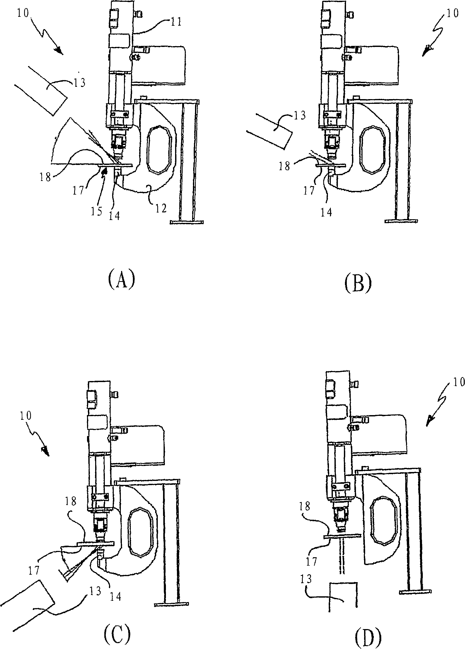
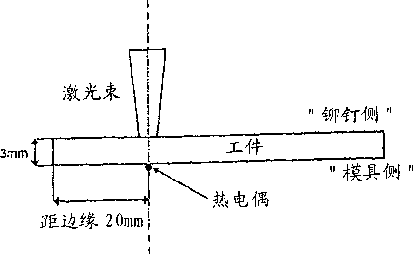
[0167] To produce crack-free joints, laser power and dwell time were varied to locally preheat the magnesium alloy component on one side of the mold to a temperature suitable to enhance its formability. Therefore, according to the predetermined heating time up to 3.6 seconds and Figure 3AVarious combinations of the elements shown in exemplarily determine the laser power output. exist Figures 3B to 3E The external and internal appearances of the corresponding joints are shown.
example 2
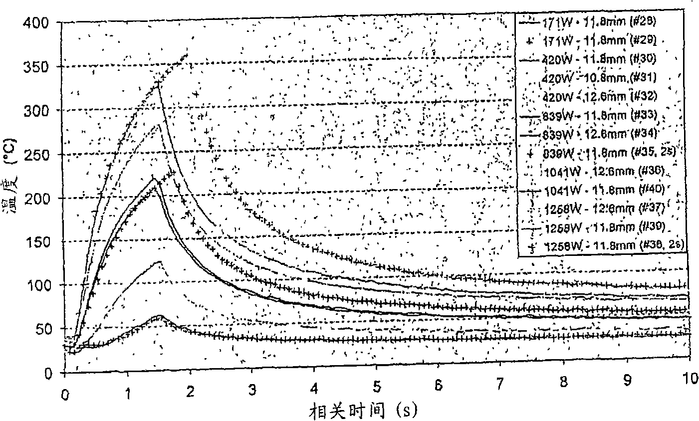
[0169] Figure 5A A typical laser preheating and SPR cycle to join two thick components is shown. The temperature curve shows the temperature drop after closing the shutter; the subsequent peak in temperature is due to the SPR tool coming into the measurement range of the infrared camera's view. Therefore, IR temperature data after SPR initiation does not indicate component temperature during joining, but provides information about the multi-stage SPR method that is consistent with clamping and rivet adjusted pressure data.
[0170] The total duration of the clamping and rivet setting phases of the SPR method was thus determined as an average of 1.47 ± 0.03 seconds over several trials of laser-assisted SPR, and by reducing the time between the start of clamping and the start of rivet setting. The time delay was reduced to 1.29 ± 0.07 seconds in subsequent trials. This can be accomplished by changing a setting parameter of the programmable logic controller of the SPR device. ...
example 3
[0179] A number of different pairs of components were joined under different conditions with and without the use of a laser to improve the formability of at least a portion of one component and its effect was evaluated. Figure 9 Images comparing joints formed with and without laser are shown in . Utilize a ratio Figures 3B to 3E Rivets of longer and / or stiffer rods as shown in Example 1 create joints. It should be noted that not only is cracking of the base element prevented when using the laser to improve the formability, but also when using the laser there is better contact of the rivet head with the surrounding material.
[0180] In Fig. 10, some static lap shear test data are presented based on single point joints for different element combinations produced using different rivets and dies. Figure 10 shows the variation in producing laser assisted SPR joints to meet strength requirements.
PUM
 Abstract
Description
Claims
Application Information
 - R&D
- Intellectual Property
- Life Sciences
- Materials
- Tech Scout
- Unparalleled Data Quality
- Higher Quality Content
- 60% Fewer Hallucinations
Browse by: Latest US Patents, China's latest patents, Technical Efficacy Thesaurus, Application Domain, Technology Topic, Popular Technical Reports.
© 2025 PatSnap. All rights reserved.Legal|Privacy policy|Modern Slavery Act Transparency Statement|Sitemap|About US| Contact US: help@patsnap.com