Multifunctional chair foundation

A technology for multi-functional chairs and underframes, which can be applied to chairs, deck chairs, and other seating furniture, etc., and can solve problems such as unsteady lifting, high labor intensity, and complex structures, and reach the applicable range where it is not easy to shake or fall. Extensive, well-structured effects

Inactive Publication Date: 2009-08-05
ZHEJIANG HAOZHONGHAO HEALTH PROD
View PDF1 Cites 13 Cited by
  • Summary
  • Abstract
  • Description
  • Claims
  • Application Information

AI Technical Summary

Problems solved by technology

[0002] The adjustment structure of the existing liftable seat can be roughly divided into three types. One is the spiral lift method, which achieves the purpose of lifting by rotating the work surface; To turn the worktop
The second is to adopt a hydraulic lifting structure to achieve the purpose of height adjustment through hydraulic jacking and unloading and lowering. Although it solves the problem that the worktable does not need to rotate with height changes, there are still manual operations, and the structure is complicated and unattractive.
The third is to use the electric lifting method, such as the Chinese patent No. 2004200427579, the name is "a kind of electric lifting device for chairs" and the Chinese patent No. 032125585, the utility model patent of "electric lifting seat" by the name, its structure is above the base A vertical single-pillar is installed to support the seat bracket, and the seat is composed of a seat cushion and a backrest. The chair is prone to shaking and even flipping; therefore, there are still problems such as unreasonable structural design and unstable lifting
But in general, there are still defects of single function and unreasonable structural design.

Method used


Image

  • Multifunctional chair foundation
  • Multifunctional chair foundation
  • Multifunctional chair foundation

Examples


Embodiment Construction

[0024] The present invention will be further described below in conjunction with the accompanying drawings and embodiments.

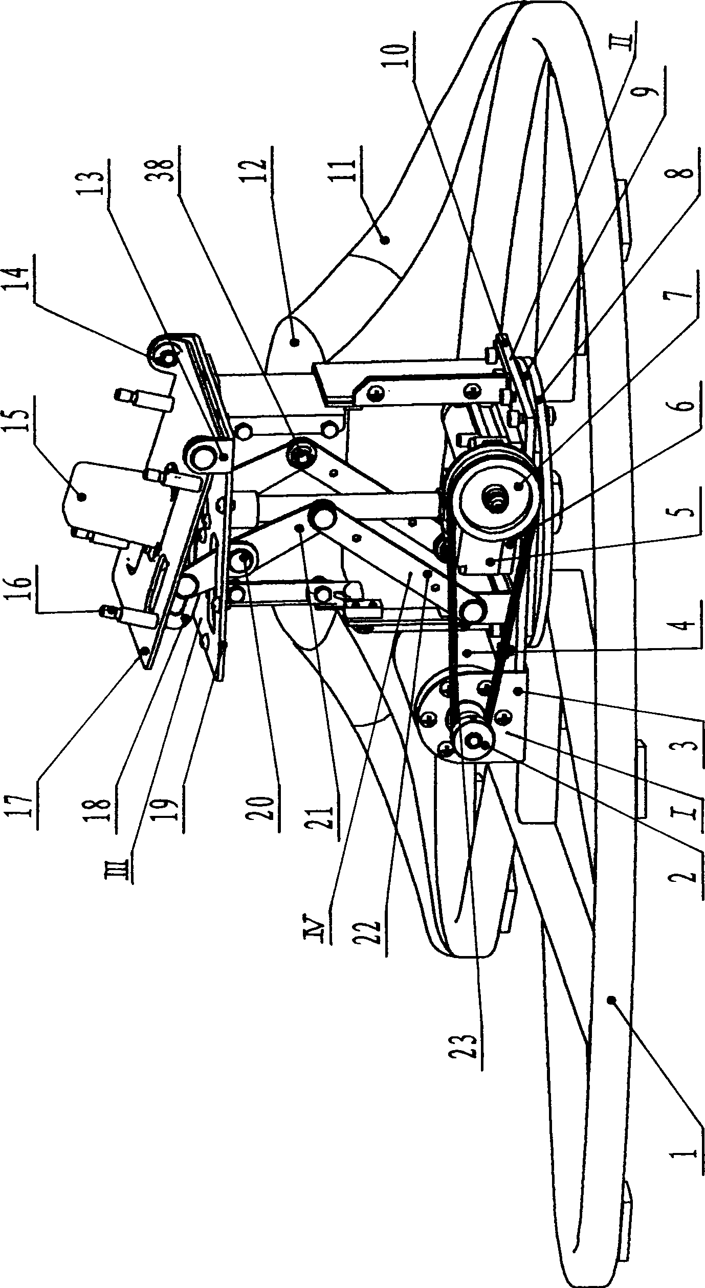
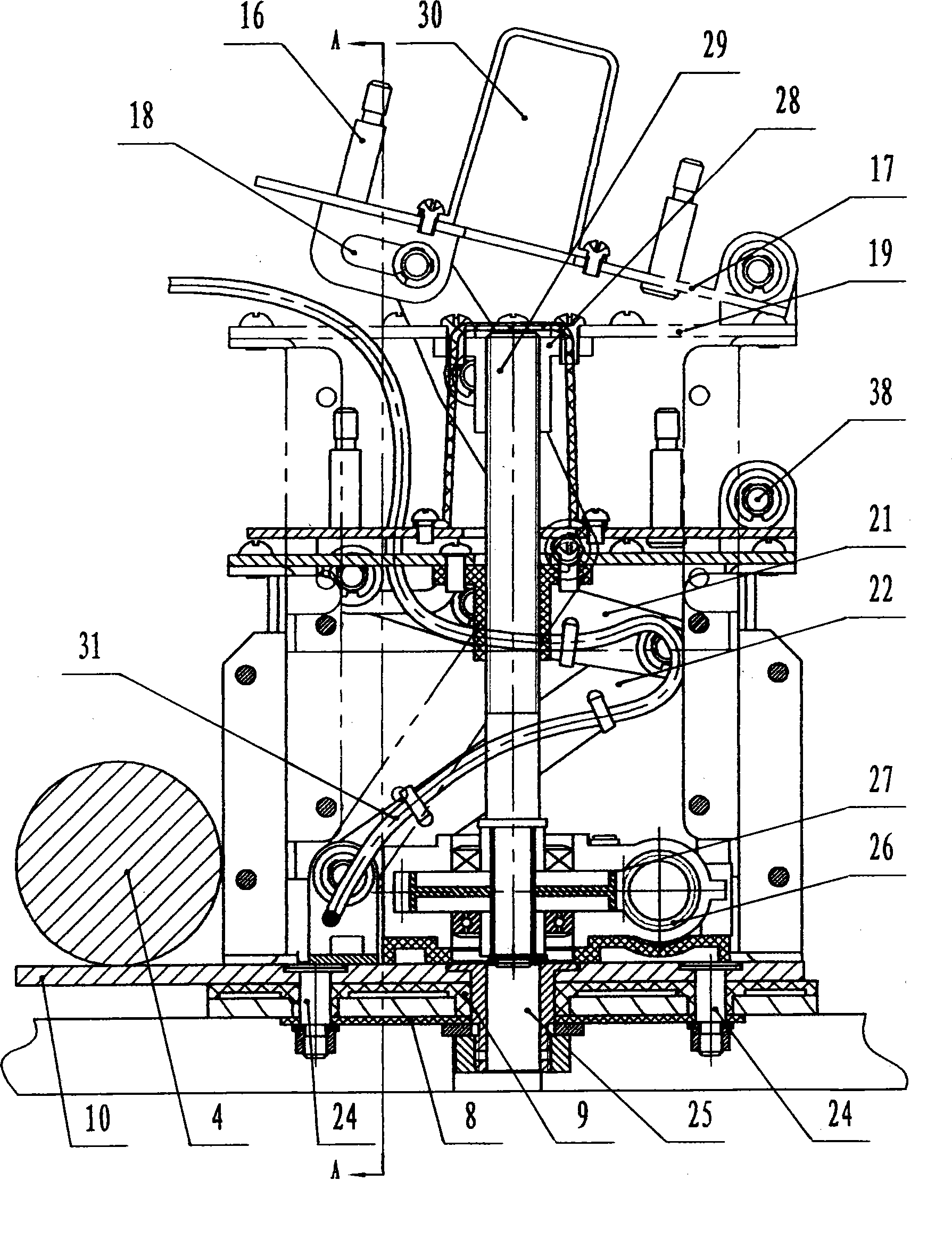
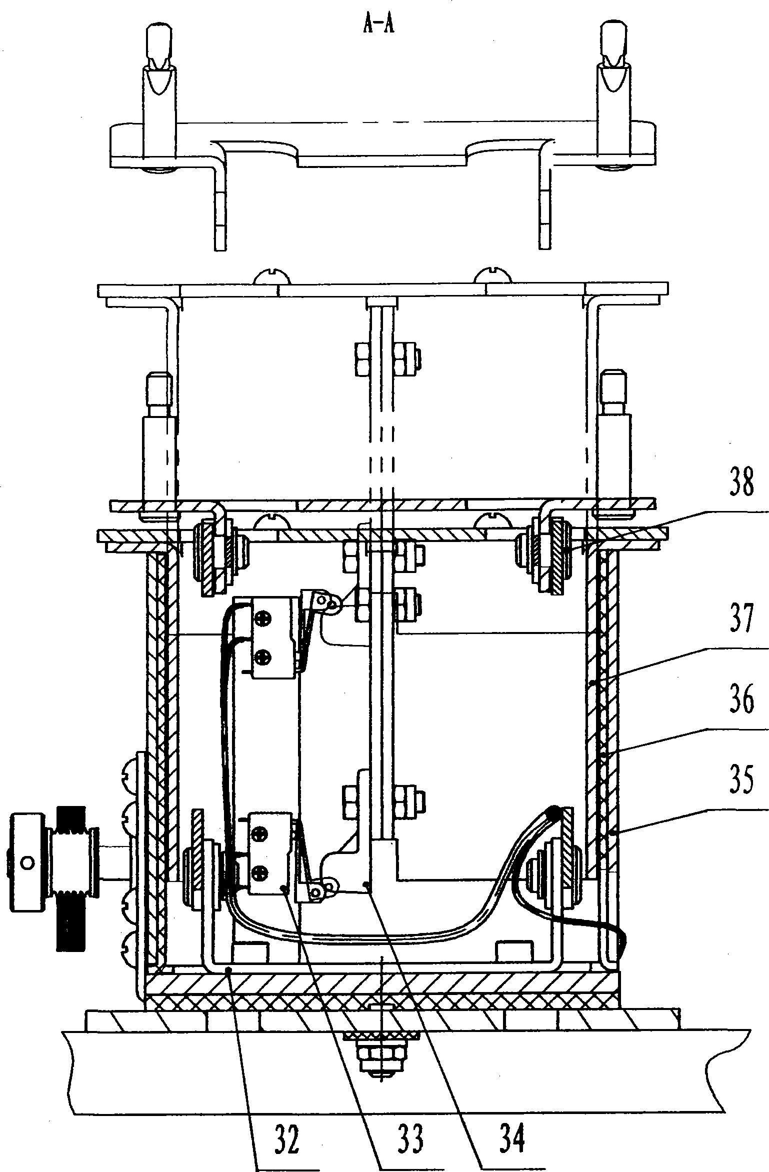
[0025] see Figure 1-Figure 3 , the present invention is provided with chassis assembly 1, chassis shell 11, electric wire assembly 3, cover plate 12, shield 30, also includes power mechanism I, rotating mechanism II, lifting mechanism III and tilting mechanism IV; Connect with screw between plate 12 and outer side plate 35, and can rotate together with outer side plate 35; Power mechanism I is installed in the bottom frame shell 11; Mechanism IV; described lifting mechanism III and tilting mechanism IV are driven by power mechanism I; rotating mechanism II is connected with lifting mechanism III and tilting mechanism IV through the connection of base plate 10 and outer plate 35 and positioning frame 32.

[0026] The rotating mechanism II of the present invention includes a base plate 10, a liner plate 9, a lower liner plate 8, a main pin 25, and a pin...


PUM


Abstract

The invention relates to a multifunctional chair base, and belongs to a part of a chair. The multifunctional chair base comprises an underframe combining piece, an underframe shell, an electric wire combining piece, a rotating mechanism and a lifting mechanism, and is characterized in that the multifunctional chair base is also provided with a cover plate, a protecting cap, an actuating unit and a tilting mechanism, wherein the rotating mechanism and the lifting mechanism are all arranged in the underframe shell; the actuating unit and the tilting mechanism are arranged in the underframe shell; the rotating mechanism is connected with the lifting mechanism and the tilting mechanism; the cover plate is connected with the lifting mechanism; and the protecting cap is connected with the tilting mechanism. The multifunctional chair base has the advantages of reasonable structural design, good configuration, beauty and utility, economy and elegance, stable lifting and multiple functions, and not only can be arranged on a massage chair, but also can be arranged on an office chair, a facial chair, a medichair, a home-use chair, and products with similar structures.

Description

technical field [0001] The invention relates to a lifting, tilting and rotating mechanism of a chair, in particular to a multifunctional chair base, which belongs to a part of the chair and is mainly suitable for medical care massage chairs. Background technique [0002] The adjustment structure of the existing liftable seat can be roughly divided into three types. One is the spiral lift method, which achieves the purpose of lifting by rotating the work surface; To turn the work surface. The second is to adopt a hydraulic lifting structure to achieve the purpose of height adjustment through hydraulic jacking and unloading and lowering. Although it solves the problem that the worktable does not need to rotate with height changes, there are still manual operations, and the structure is complicated and unattractive. . The third is to use the electric lifting method, such as the Chinese patent No. 2004200427579, the name is "a kind of electric lifting device for chairs" and th...

Claims


Application Information

Patent Timeline
Patent Type & Authority Applications(China)
IPC IPC(8): A47C1/00A47C3/18A47C3/20A47C1/032
Inventor 周国海李国荣
Owner ZHEJIANG HAOZHONGHAO HEALTH PROD
Why Eureka
Try Eureka