Vertical rolling washing machine and control method thereof

A washing machine and rolling washing technology, which is applied to other washing machines, washing machines with containers, washing devices, etc., can solve the problems of limited friction and low washing degree of clothes, and achieve reduced water consumption, free washing methods, and high washing degree Effect

Inactive Publication Date: 2009-08-05
叶小舟 +1
View PDF3 Cites 40 Cited by
  • Summary
  • Abstract
  • Description
  • Claims
  • Application Information

AI Technical Summary

Problems solved by technology

[0008] Although the above comparative patent can reduce the water consumption of laundry to a certain extent, when the inner tub rotates at a high speed to perform the washing procedure, the washing liquid and the clothes rotate together under the action of the centrifugal force generated by the inner tub. Rotating at a relatively fixed vertical height, the friction between the clothes and the washing liquid, the clothes and the inner tub is relatively limited, and the washing degree of the clothes is not high
[0009] In addition, the drainage pipeline of the washing machine is a double-layer structure with an inner bucket for drainage. It can only be drained by intermittent dehydration in multiple cycles of off-stop-off-stop, so that water can be discharged from the drain hole at the bottom of the bucket.

Method used


Image

  • Vertical rolling washing machine and control method thereof
  • Vertical rolling washing machine and control method thereof
  • Vertical rolling washing machine and control method thereof

Examples


Embodiment 1

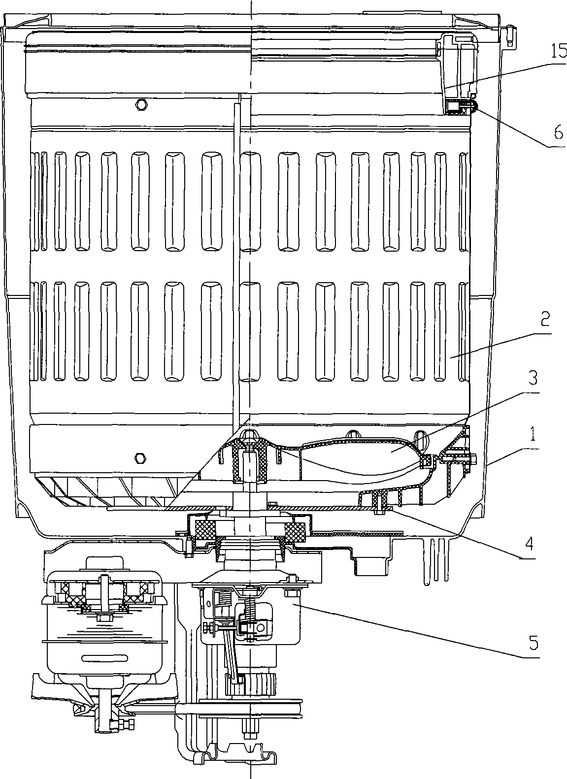
[0054] Example 1, such as Figure 1 to Figure 5 As shown, the vertical rolling washing machine described in this embodiment has a box body, and an outer tub 1 , a washing inner tub 2 , a chassis assembly 4 and a driving mechanism 5 are arranged inside the box body.

[0055] The outer tub 1 is connected with the box body through a suspender, and the chassis assembly 4 is connected with the washing inner tub 2 .

[0056] A washing inner tub 2 is arranged inside the outer tub 1 , the chassis assembly 4 is at least connected to the washing inner tub 2 , and a balancing ring 15 is arranged at the opening of the washing inner tub 2 top.

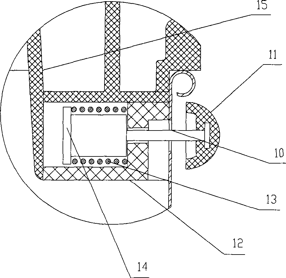
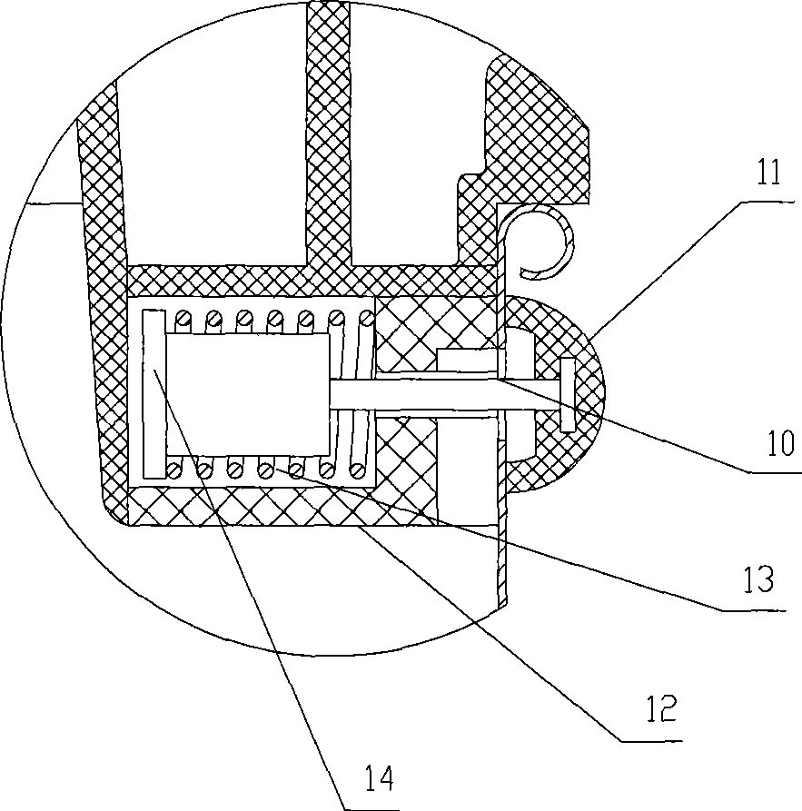
[0057] For washing the inner tub 2, several dehydration drainage holes 10 evenly distributed in the horizontal circumferential direction are provided only under the balance ring on the top of the tub wall, and a centrifugal drainage valve 6 is arranged at each dehydration drainage hole 10 so as to control the dehydration drainage holes 10. It is o...


PUM


Abstract

The invention relates to a vertical-drum washing machine and a vertical-drum washing method thereof. A washing inner drum rotates and drives washing liquid and clothes to press a washing drum wall and ascend along the washing drum wall. The clothes are washed by the washing liquid while generating friction with the inner drum wall in the washing mode, and the clothes are mutually rubbed and beaten so as to achieve the washing aim to a maximum extent and further improve the cleanliness. The vertical-drum washing machine is mainly provided with a box body, wherein an outer drum, the washing inner drum, an underpan assembly and a driving mechanism are arranged in the box body; only a plurality of dewatering drain holes are uniformly distributed in the horizontal circumferential direction below a balance ring at the top of the drum wall of the washing inner drum, a centrifugal drain valve is arranged in each dewatering drain hole so that the dewatering drain holes are controlled to open when the washing inner drum achieves a set start speed and close when the speed of the washing inner drum is lower than the set start speed; and the driving mechanism is connected with the bottom of the drum wall of the washing inner drum to drive the washing inner drum to make washing rotation and dewatering rotation.

Description

technical field [0001] The invention relates to a full-automatic washing machine, which adopts the structure of no water storage in the outer tub to realize the vertical rolling washing method inside the inner tub. The washing liquid and clothes rise and rub against each other along the wall of the washing inner tub under the action of centrifugal force, and the washing liquid finally washes. Discharge from the top of the washing inner tub for spin operation. Background technique [0002] The fully automatic washing machines that are more commonly produced and used at present include an inner tub for washing and an outer tub for water storage. There is no seal between the inner tub and the outer tub to form an ineffective space for water storage, thereby increasing the water consumption for washing ordinary clothes. [0003] For example, the prior patent disclosing the following specific scheme, patent No. 01114767.9, is called a single-tub fully automatic washing machine, w...

Claims


Application Information

Patent Timeline
Patent Type & Authority Applications(China)
IPC IPC(8): D06F23/04D06F37/12D06F39/08
Inventor 叶小舟刘劲旋
Owner 叶小舟
Why Eureka
Try Eureka