Disperse barrel construction structure system

A technology of building structure and dispersion cylinder, which is applied in building components, building structures, buildings, etc., to achieve the effects of excellent seismic performance, clear force transmission path, and clear structural component performance.

Inactive Publication Date: 2009-08-05
OCEAN UNIV OF CHINA
View PDF0 Cites 10 Cited by
  • Summary
  • Abstract
  • Description
  • Claims
  • Application Information

AI Technical Summary

Problems solved by technology

The disadvantage of the beam-tube structure system is that the layout of the building has great limitations

Method used


Image

  • Disperse barrel construction structure system
  • Disperse barrel construction structure system
  • Disperse barrel construction structure system

Examples


Embodiment 1

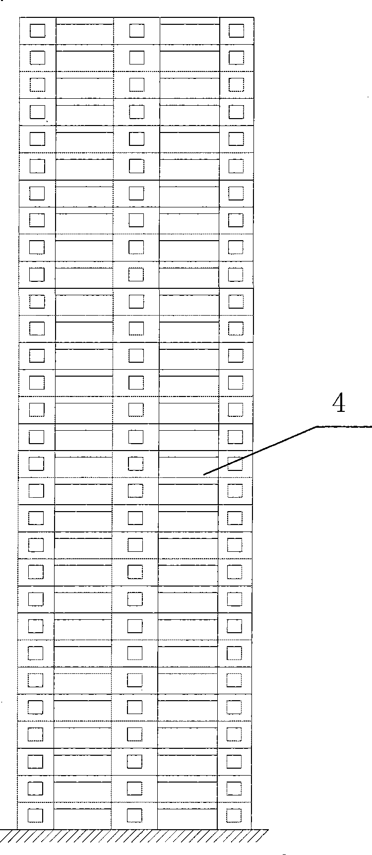
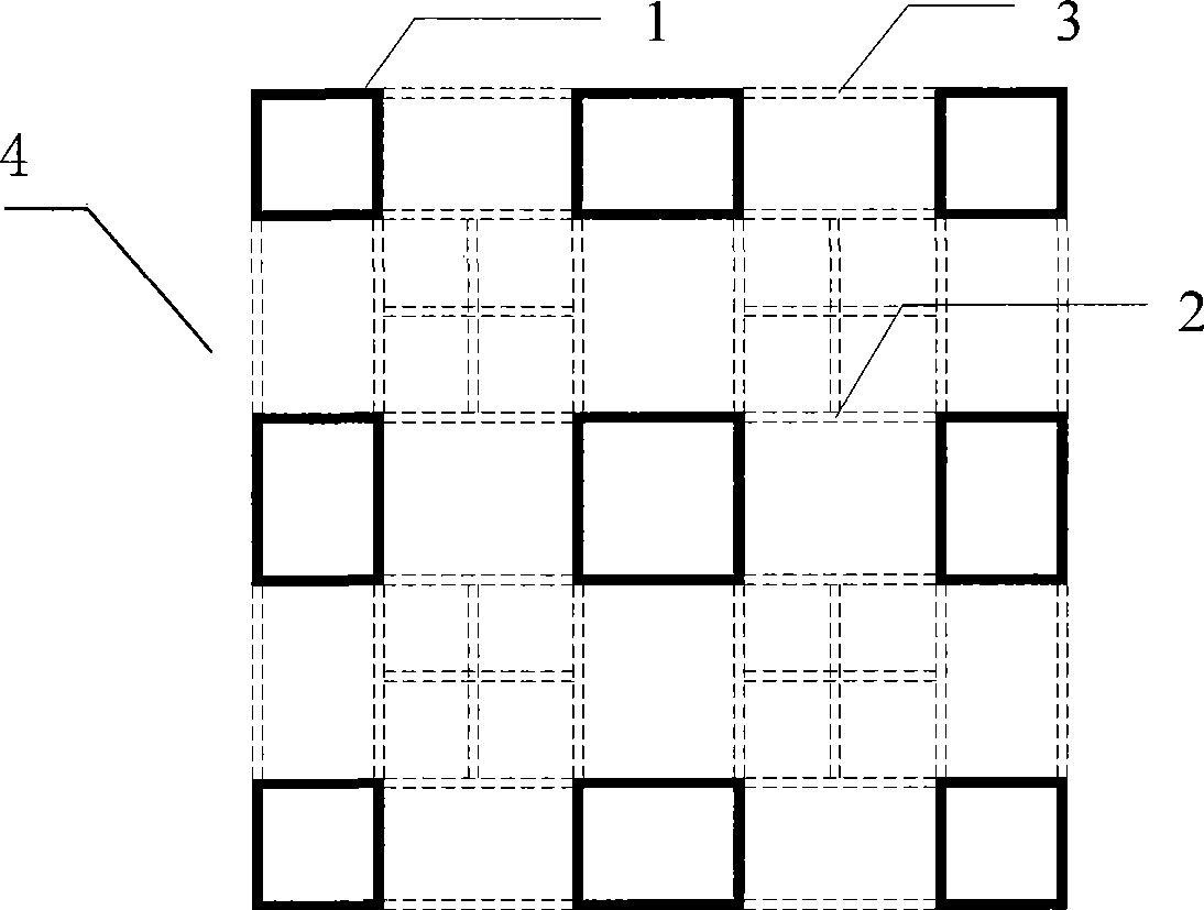
[0029] Shear wall cylinders 1 are arranged at intervals on each floor 4 of the building, and the shear wall cylinders 1 are surrounded by shear walls, and adjacent shear wall cylinders 1 are connected by beams. The shear wall cylindrical body 1 on the upper floor is located directly above the shear wall cylindrical body 1 on the lower floor. The beam includes an external skirt beam 3 and a connecting beam 2. The external skirt beam 3 connects the outer shear wall cylinder 1 of each floor 4 of the building, and the connecting beam 2 connects the internal shear force of each floor 4 of the building. Wall cylinder connection.

Embodiment 2

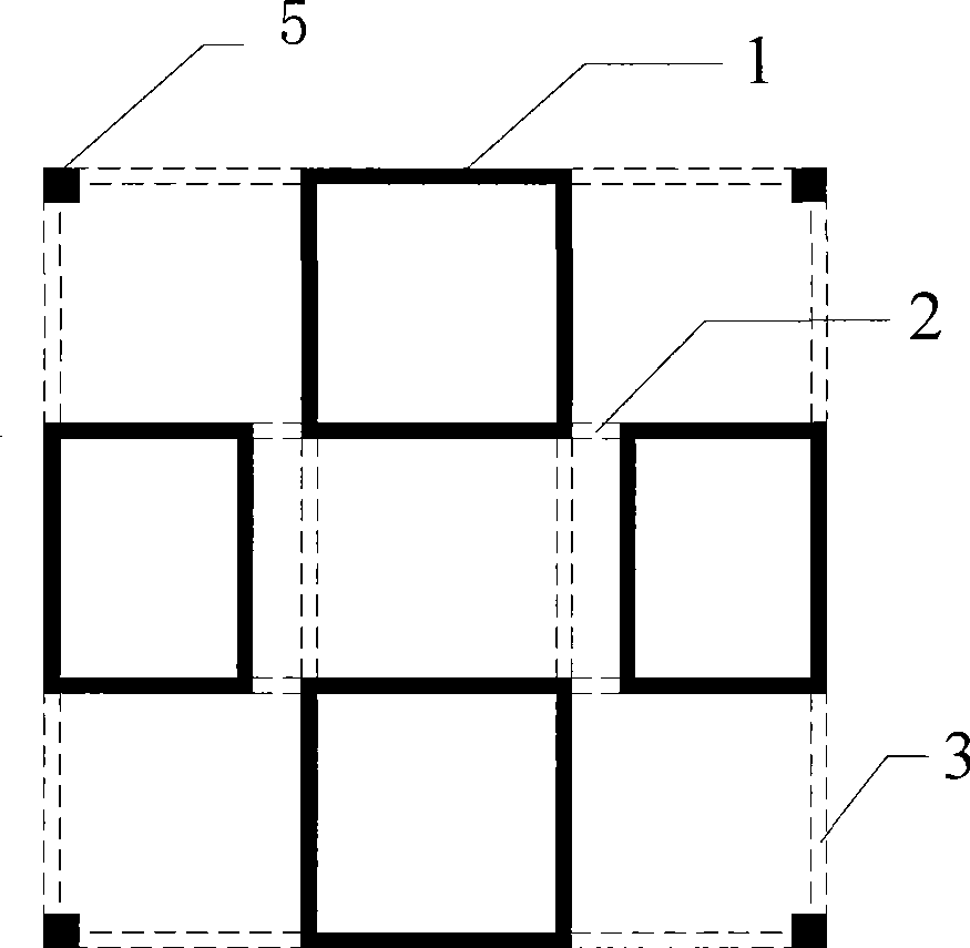
[0031] When the building needs to be flexibly arranged, and it is not easy to directly connect the shear wall cylinders 1 through beams, a small number of columns 5 can be arranged at necessary positions.


PUM


Abstract

The invention relates to a structural configuration form of a building, in particular to a novel structural system of a building. For the scattered tube building structural system, shearing wall tube bodies are arranged inside the building in a scattering mode; and the adjacent shearing wall bodies are connected by beams. The invention has definite force transfer path, flexible structural configuration, full utilization of structural materials and uniform vertical rigidity of the structure; and under the condition of earthquake, the performance of structural members is definite and the torsional effect of the structure is not obvious, so the invention is easy to be designed into a high-rise building structure with excellent anti-seismic performance.

Description

technical field [0001] The invention relates to a structural arrangement form of a building, in particular to a new structural system of the building. Background technique [0002] High-rise buildings are developed with the development of social production and the needs of people's lives, and are the result of commercialization, industrialization and urbanization. Since the 1970s, high-rise buildings in mainland China have developed greatly, mainly residential buildings, hotels, and office buildings. High-rise buildings have the advantages of small footprint, saving municipal engineering costs, and saving demolition costs. [0003] High-rise building structures must simultaneously bear vertical loads such as self-weight and service loads, horizontal wind loads, and earthquakes. Compared with multi-storey building structures in which vertical loads play a controlling role, the effect of horizontal wind loads gradually increases with the increase of building height. In tall ...

Claims


Application Information

Patent Timeline
Patent Type & Authority Applications(China)
IPC IPC(8): E04B1/00E04B1/18E04B2/00
Inventor 蒋济同杨松杜德润孟珣
Owner OCEAN UNIV OF CHINA
Why Eureka
Try Eureka