Metal framework reinforced plastic composite pipes and method for manufacturing the same

A technology of metal skeleton and reinforced plastic, which is applied in the direction of pipes, rigid pipes, pipeline connection layout, etc., can solve the problems of not meeting the sealing requirements, achieve the effects of preventing corrosion, convenient construction, and improving mechanical strength

Inactive Publication Date: 2009-08-05
甘国工
View PDF2 Cites 16 Cited by
  • Summary
  • Abstract
  • Description
  • Claims
  • Application Information

AI Technical Summary

Problems solved by technology

Because the pipe wall and the inner cavity surface of the pipe connector are both conical surfaces, the hot melt on the corresponding conical surface when they are heated and socketed is extruded instead of pushed out of the connecting surface, so there is not only enough melt, but also enough They are well welded to each other, but there are still weak links between the metal skeleton of the pipe end face and the plastic inner layer and the end of the plastic pipe fittings, especially when the metal composite plastic pipe is used in harsh environments, such as hot water transportation, but due to the metal There is an order of magnitude difference in the thermal linear expansion coefficient of the two materials and the plastic, and the long-term alternating heat and cold will cause cracks between the plastic and the metal skeleton at the weak link of the connection due to thermal expansion and contraction, and the sealing requirements cannot be met.

Method used


Image

  • Metal framework reinforced plastic composite pipes and method for manufacturing the same
  • Metal framework reinforced plastic composite pipes and method for manufacturing the same
  • Metal framework reinforced plastic composite pipes and method for manufacturing the same

Examples


Embodiment 1

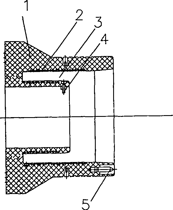
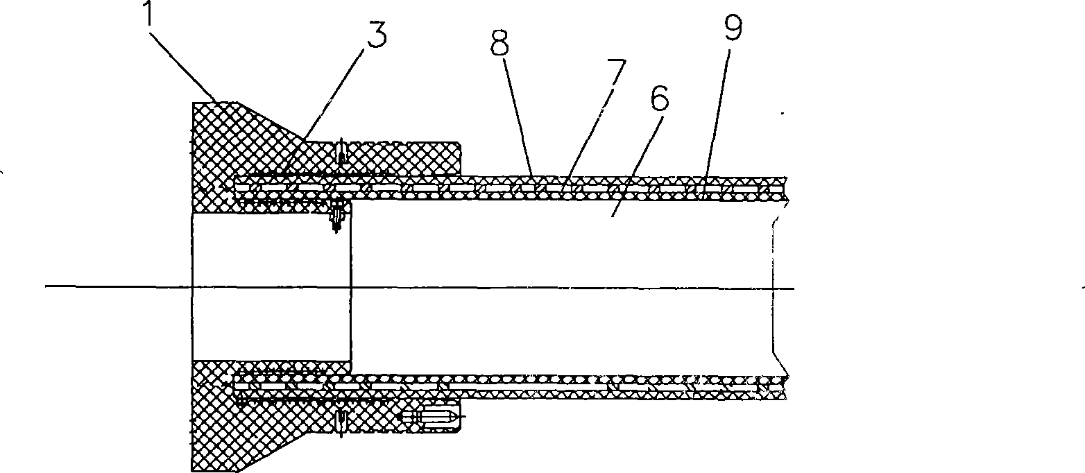
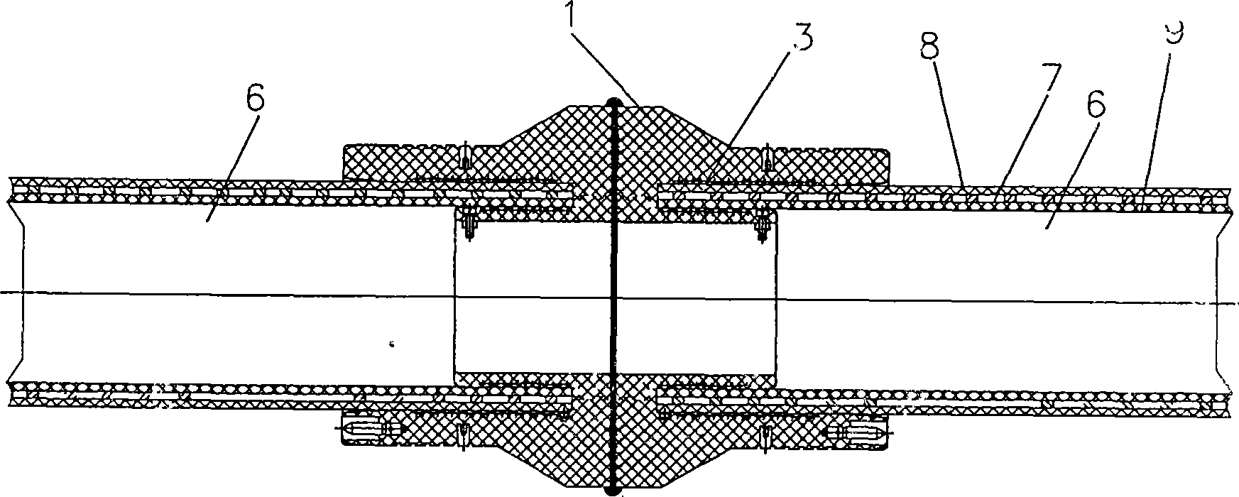
[0034] Figure 1 ~ Figure 3 Figure 1 of this example is given. In this embodiment 1, a two-way pipe connector 1 that satisfies the working pressure is first produced. There is an annular U-shaped socket 3 in the pipe connector 1, and heating wires 2 are arranged on both sides of the socket 3. The heating wire passes through the first A terminal 4 and a second terminal 5 are energized. Such as figure 2 Shown, there is the perforated steel plate metal skeleton 7 with holes covered by the plastic outer layer 8 and the plastic inner layer 9 in the metal skeleton composite plastic pipe 6 (or the warp direction steel wire is wound with the latitude steel wire and its contact point is welded Formed cylindrical metal skeleton, or steel wire left-handed and / or right-handed helical winding formed cylindrical metal skeleton, or steel wire braided cylindrical metal skeleton, or longitudinally butted or lapped with aluminum strips and Cylindrical metal skeleton formed by welding). The...

Embodiment 2

[0036] Figure 4 , Figure 5 , Figure 6 Figure 2 of Embodiment 2 of the present invention is given. Embodiment 2 is basically the same as Embodiment 1. The difference is that the pipe connector 1 has no electric heating wire, and the ring-shaped U-shaped socket 3 in the pipe connector 1 completely covers the plastic outer layer and plastic inner layer of the end of the metal skeleton reinforced plastic composite pipe and the end face of the pipe. The method melts and connects the pipe connector and the metal skeleton reinforced plastic composite pipe.

Embodiment 3

[0038] Figure 7 , Figure 8 Figure 3 of Embodiment 3 of the present invention is given. Embodiment 3 is basically the same as Embodiment 1. The difference is that when the pipe connector 1 is melt-connected with the metal skeleton reinforced plastic composite pipe 6, the inner hole support fixture 10 is used to press the inner wall of the pipe connector to the plastic inner layer 9 in the composite pipe 6, and the outer ring is used to The clamp 22 presses the outer layer wall in the pipe connector to the plastic outer layer 8 in the composite pipe 6, and exerts pressure on the fusion connection surface, so that the connection of the fusion connection surface is more firm and reliable. There are two movable rings 11 and 12 hinged to each other in the inner hole support fixture 10, and an adjusting mechanism 13 positioned in the movable ring.


PUM


Abstract

The invention provides a metal skeleton reinforced plastic composite pipe which is provided with a pipeline connecting piece which can connect a pipeline with another pipeline or the pipeline with a pipeline joint to form a pipe network in satisfying the working pressure. The end of the pipeline connecting piece connected with the metal skeleton reinforced plastic composite pipeline is provided with an annular U-shaped bell and spigot hole which totally wraps the plastic external layer and the plastic internal layer of the end of the metal skeleton reinforced plastic composite pipeline and the end surface of the metal skeleton reinforced plastic composite pipeline; and the pipeline connecting piece is connected with the metal skeleton reinforced plastic composite pipeline in a hot melting way or electric melting way. The annular U-shaped bell and spigot hole of the pipeline connecting piece totally and tightly wraps the plastic external layer and the plastic internal layer of the end of the metal reinforced composite pipeline and the end surface of the metal skeleton reinforced plastic composite pipeline, the connection is firm and reliable without leakage, the connection position has high mechanical strength and prevents fluid from entering into a metal skeleton to corrode the metal skeleton, and the service life of the pipeline is long. The invention further provides a method for manufacturing the metal skeleton reinforced plastic composite pipe.

Description

Technical field: [0001] The invention relates to a metal skeleton reinforced plastic composite pipe and a manufacturing method thereof. Background technique: [0002] The known metal-composite plastic pipes are connected by mechanical clamping method, such as aluminum-plastic composite pipes, and the electric heating wires distributed in the inner cavity of the socket of the pipe fitting connector are used to electrically heat the cylindrical connection surface or taper of the pipe and pipe fittings. The connection surface makes the two sides melt and connect, and there is also a method of thermally melting the conical surface between the pipe and the pipe fitting together with the stepped end surface of the pipe fitting cavity by using the method of rotating friction to generate heat and melt connection, such as patent application number 200510021077. 03225501, this patent discloses a heat-melt connection structure of aluminum-plastic composite pipes, and there is also pate...

Claims


Application Information

Patent Timeline
Patent Type & Authority Applications(China)
IPC IPC(8): F16L9/147F16L47/02F16L47/06
Inventor 甘国工
Owner 甘国工
Why Eureka
Try Eureka