Pneumatic pressure regulator

A pressure regulation and pressure chamber technology, applied in the field of pressure regulating valves, can solve problems such as affecting the regulating pressure, and achieve the effect of avoiding damage or deformation

Inactive Publication Date: 2009-08-05
ABB (SCHWEIZ) AG
View PDF3 Cites 2 Cited by
  • Summary
  • Abstract
  • Description
  • Claims
  • Application Information

AI Technical Summary

Problems solved by technology

This has a disadvantageous effect on the constancy of the control pressure, since an already small change in the pretension of the control spring leads to impermissible deviations of the set control pressure
These impermissible deviations are particularly disadvantageous in the first place and remain hidden and remain unknown as a cause of apparent disturbances of downstream devices.

Method used


Image

  • Pneumatic pressure regulator

Examples


Embodiment Construction

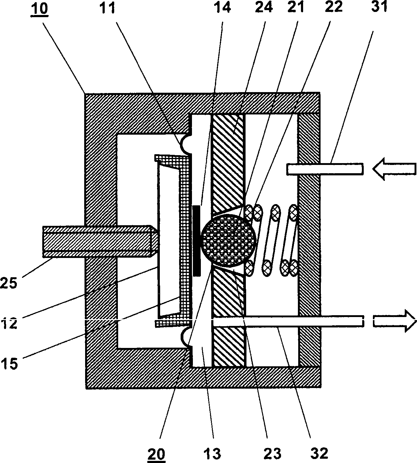
[0017] The pressure regulating valve 10 has a pressure chamber 13 which is surrounded by a regulating diaphragm 11 and a housing wall 24 opposite it.

[0018] Arranged in the housing wall 24 is a control valve 20 which is formed by a dimensionally stable ball 21 which is loaded by a spring 22 in a conical bore 23 which tapers in the direction of the regulating diaphragm 11 . The side of the ball 21 facing the spring 22 is supplied with unregulated pressure medium 31 .

[0019] The adjusting diaphragm 11 is supported non-positively on a pressure plate 15 which is connected to a rotationally symmetrical adjusting spring 12 . The adjusting spring 12 is supported at its center of gravity on an adjusting screw 25 . In a first embodiment of the invention, the adjusting spring 12 is designed as a disc spring. In a preferred embodiment, the adjusting spring 12 is designed as a spring star for a small adjusting pressure 32 . It can be provided here that the pressure plate 15 is non-...


PUM


Abstract

The disclosure relates to a pneumatic pressure regulator (10) for pressure adjustment (32) of a regulating pressure in a pressure chamber (13) with a regulator membrane (11) which is held in force equilibrium by a regulator spring (12) and the regulating pressure (32), wherein the regulator membrane (11) is coupled with a control valve (20) in such a way that the control valve (20) opens or closes in dependence upon the actual regulating pressure (32). For increasing the stability and the constancy of the regulating pressure it is proposed to form the control valve (20) by a dimensionally stable ball (21) which is seated in a loaded manner by means of a spring in a conical bore (23) which tapers in the direction of the regulator membrane (11) and is in a housing wall which lies opposite the regulator membrane (11) with regard to the pressure chamber (13), the regulator membrane (11) having a reinforcement in the contact region with the ball, and the ball following the movement of the regulator membrane in its normal direction. The diameter of the ball is relative to the conicity of the bore, which allows one segment of the bore to expend into the pressure chamber along the adjustment direction of the membrane.

Description

technical field [0001] The invention relates to a pressure regulating valve for regulating a regulating pressure, which comprises a regulating diaphragm which is force-balanced by a regulating spring and the regulating pressure. Background technique [0002] Such pneumatic pressure regulating valves are generally known and serve to regulate a constant control pressure independently of pressure fluctuations of the supplied pressure medium. [0003] A pneumatic pressure regulating valve is known from WO 05088417 A1, the throughflow of which can be changed automatically in relation to pressure, which comprises a regulating diaphragm, which is loaded by the reference pressure, the gas pressure and the regulating spring, so that in When the pressure difference changes, the regulating diaphragm is moved and the regulating diaphragm itself or the closing body actuated by it changes the flow rate through the discharge cross-section, and the structure adjacent to the discharge cross-...

Claims


Application Information

Patent Timeline
Patent Type & Authority Applications(China)
IPC IPC(8): G05D16/06
CPCG05D16/0658Y10T137/0396Y10T137/7793
Inventor H·米勒
Owner ABB (SCHWEIZ) AG
Why Eureka
Try Eureka