Combinded processing lathe and its tool post

一种复合加工、刀架的技术,应用在车床、六角车床、金属加工等方向,能够解决限制很多、限制、不能充分缩短加工每个工件所需的时间等问题,达到减少加工自由度、缩短时间的效果

Inactive Publication Date: 2009-08-05
CITIZEN WATCH CO LTD
View PDF5 Cites 18 Cited by
  • Summary
  • Abstract
  • Description
  • Claims
  • Application Information

AI Technical Summary

Problems solved by technology

[0025] However, with this turret, since each turret cannot be indexed independently, it is also not possible to index the other turret while machining with a tool in one turret. Rotate, no pre-selection of the tool to be used for subsequent machining
[0026] Therefore, none of the above devices can sufficiently shorten the non-machining time, that is, the time required for tool selection, and cannot sufficiently shorten the time required for machining each workpiece.
In addition, from the perspective of processing freedom, there are many restrictions
[0027] As mentioned above, none of the conventional compound machining lathes can shorten the time required to select a tool through its tool holder, or the degree of freedom in machining is insufficient, and there is a limit to shortening the time required for machining each workpiece.

Method used


Image

  • Combinded processing lathe and its tool post
  • Combinded processing lathe and its tool post
  • Combinded processing lathe and its tool post

Examples


Embodiment Construction

[0064] Hereinafter, preferred embodiments of the present invention will be described with reference to the drawings.

[0065] First, through Figure 1 ~ Figure 3 A configuration example of the composite machining lathe according to the invention and a basic configuration example of the tool holder according to the invention included in the composite machining lathe will be described.

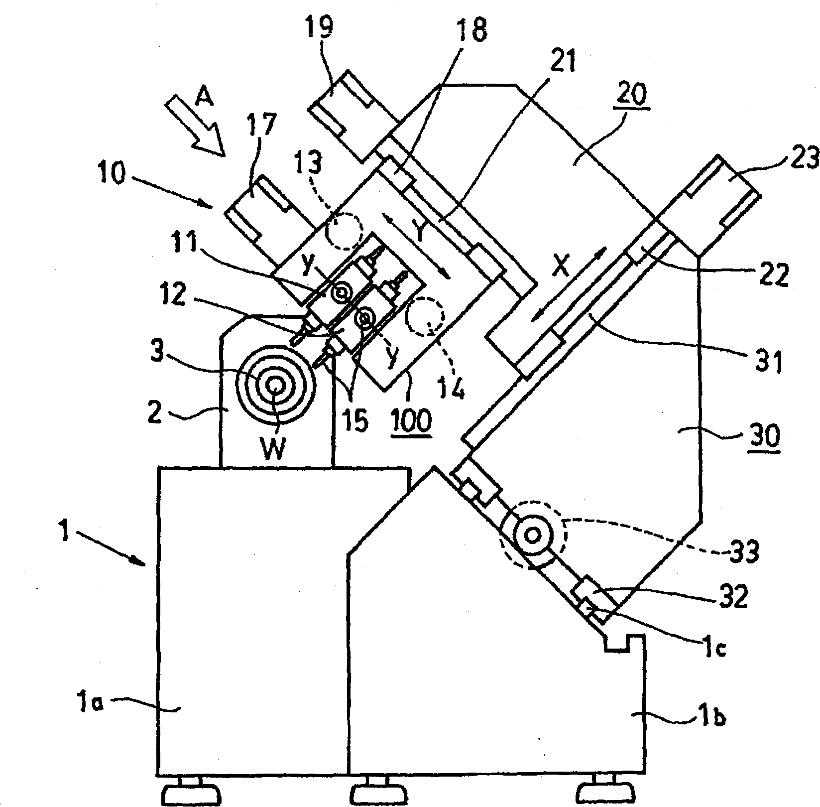
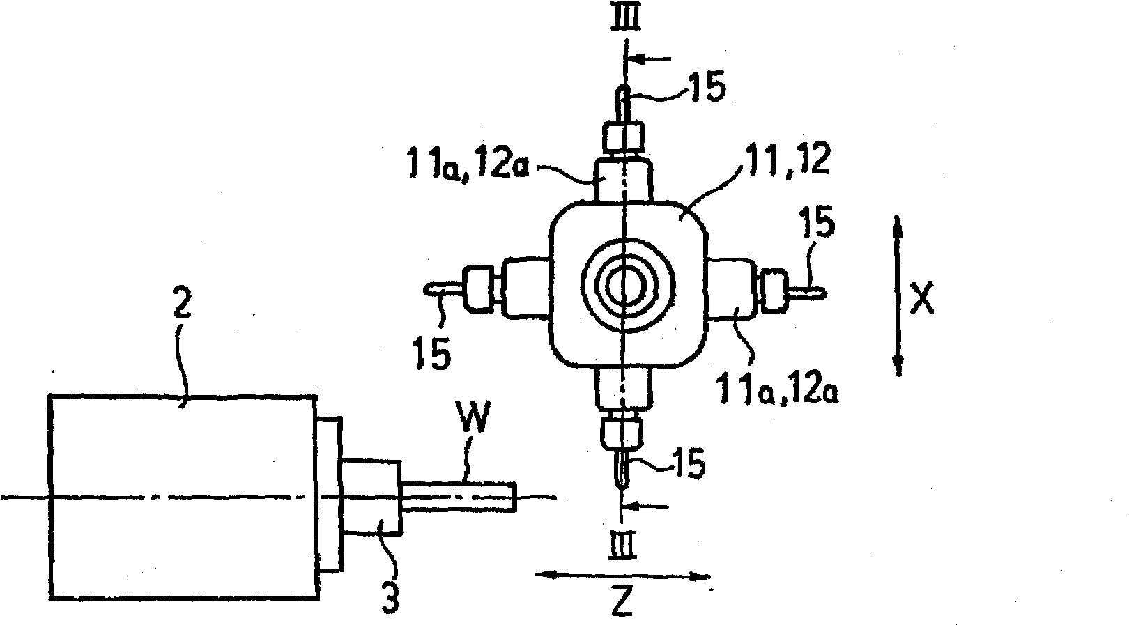
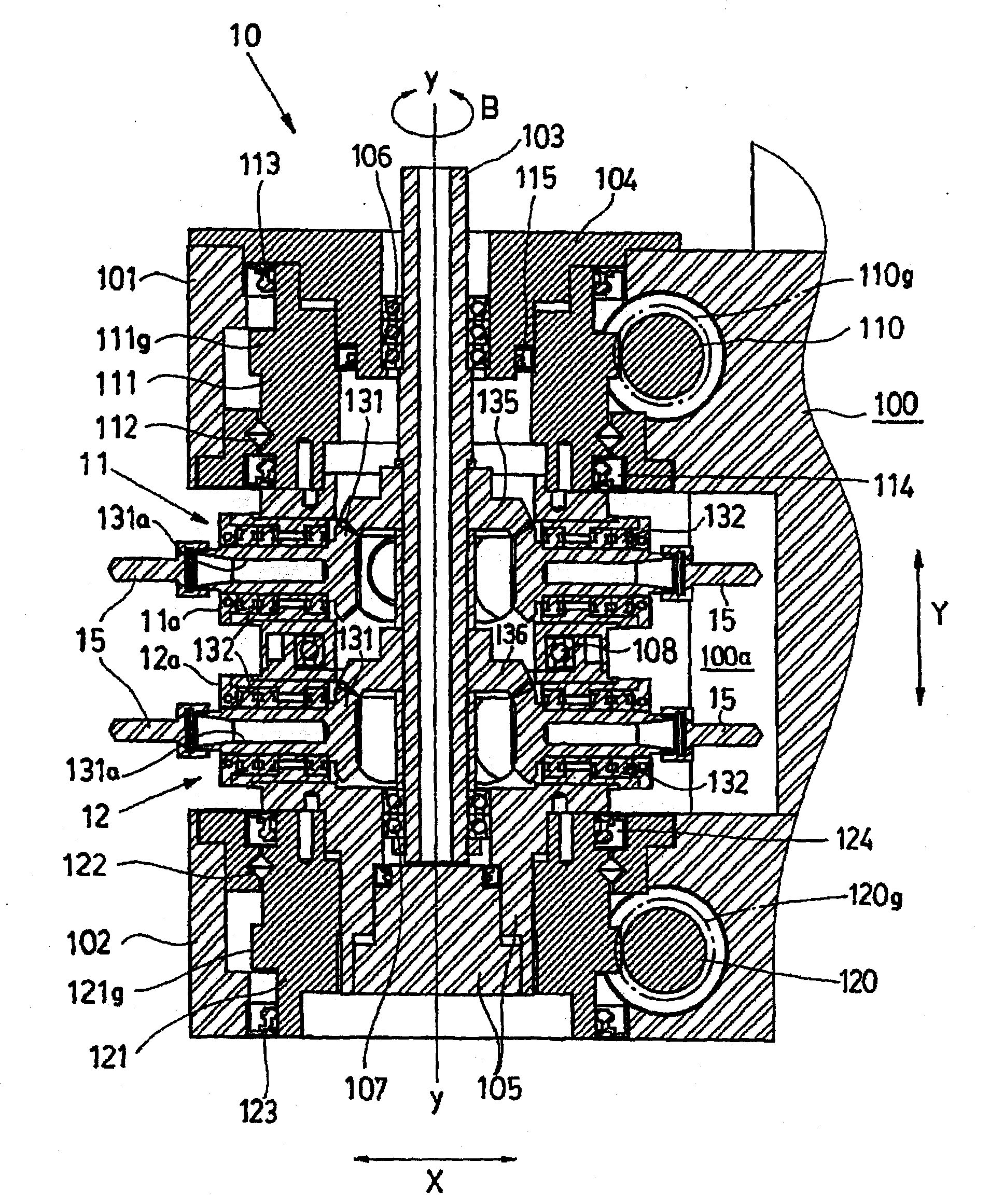
[0066] figure 1 It is a schematic front view showing the overall configuration of this compound machining lathe, figure 2 means from figure 1 The relationship between the turret tool holder and the main shaft of the tool holder seen in the direction of the middle arrow A. image 3 Zoomed in along figure 2 The overall longitudinal section of the tool holder on the line III-III shows its internal structure.

[0067] exist figure 1 In this case, a headstock 2 supporting a freely rotatable spindle 3 is placed on a headstock support portion 1 a of a machine bed 1 . The headstock 2 can be mov...


PUM


Abstract

The invention relates to a compound working lathe and turrets thereof. Turrets (11, 12), which can rotate about a common axis (y-y) and on the outer peripheral surfaces of which a plurality of tools (15) are radially installed, are disposed along the axis (y-y) in a turret housing (100). Respective turrets (11, 12) can be dividedly rotated by separate turret driving motors (13, 14).

Description

technical field [0001] The present invention relates to a compound machining lathe for performing multiple different machinings on workpieces, and a tool holder installed on the lathe and capable of selecting and holding various tools used for machining. Background technique [0002] Generally, a lathe performs machining by bringing a tool such as a turning tool into contact with a workpiece that is rotationally driven by a spindle, that is, a workpiece. [0003] Furthermore, lathes that perform multiple different processes on workpieces, that is, composite processes, are often used. For example, various lathes and machine tools disclosed in Patent Documents 1 to 5 are well known. [0004] [Patent Document 1]: Japanese Patent Application Laid-Open No. 11-138374 [0005] [Patent Document 2]: Japanese Patent Application Laid-Open No. 10-15702 [0006] [Patent Document 3]: Specification of European Patent Application Publication No. 1270145 [0007] [Patent Document 4]: Japa...

Claims


Application Information

Patent Timeline
Patent Type & Authority Applications(China)
IPC IPC(8): B23B29/24B23B3/16B23B21/00
CPCB23Q39/024B23Q2039/004B23B3/165B23Q39/028B23Q16/025Y10T29/5153Y10T29/5155Y10T29/5124Y10T82/2587Y10T29/5109Y10T82/2508B23B29/24B23B3/16B23B29/00
Inventor 渡边雅彦青柳厚志
Owner CITIZEN WATCH CO LTD
Why Eureka
Try Eureka