Frequency-variable acoustic film resonator, filter and communication apparatus using the same

A resonator and variable technology, applied in the field of filters, can solve the problems of affecting the characteristics of sound film resonators, deterioration of filter characteristics, and inability to be variable at the same time

Inactive Publication Date: 2009-08-05
PANASONIC CORP
View PDF2 Cites 18 Cited by
  • Summary
  • Abstract
  • Description
  • Claims
  • Application Information

AI Technical Summary

Problems solved by technology

Therefore, in the case where a capacitor is connected in series with the acoustic thin film resonator, the difference between the resonance frequency and the antiresonance frequency of the acoustic thin film resonator becomes small, and the filter characteristics deteriorate
Furthermore, in the case where a capacitor is connected in parallel with the...

Method used


Image

  • Frequency-variable acoustic film resonator, filter and communication apparatus using the same
  • Frequency-variable acoustic film resonator, filter and communication apparatus using the same
  • Frequency-variable acoustic film resonator, filter and communication apparatus using the same

Examples


Embodiment approach 1

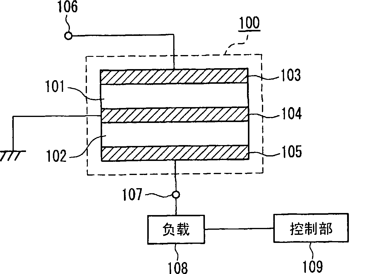
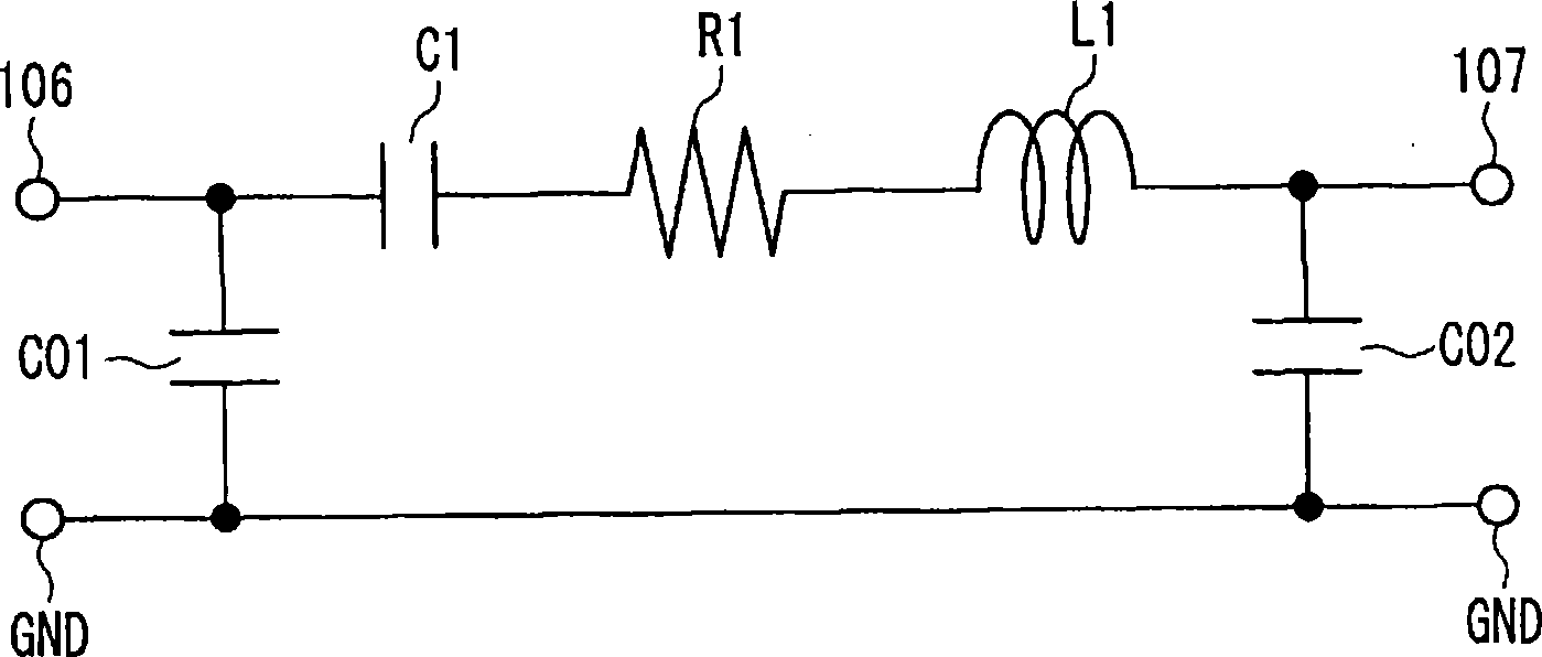
[0096] Figure 1A It is a block diagram of the frequency variable acoustic thin film resonator according to Embodiment 1 of the present invention. Figure 1B is its equivalent circuit diagram.

[0097] exist Figure 1A Among them, the acoustic thin film resonator 100 has a first piezoelectric body 101 and a second piezoelectric body 102 which are stacked. The first piezoelectric body 101 is sandwiched between the first electrode 103 and the second electrode 104 , and the second piezoelectric body 102 is sandwiched between the second electrode 104 and the third electrode 105 . The input terminal 106 is connected to the first electrode 103 , the second electrode 104 is connected to GND, and the output terminal 107 is connected to the third electrode 105 . A load 108 is also connected to the third electrode 105 , and the value of the load 108 is controlled by a control unit 109 .

[0098] like Figure 1B As shown, the acoustic thin film resonator 100 can be represented by an...

Embodiment approach 2

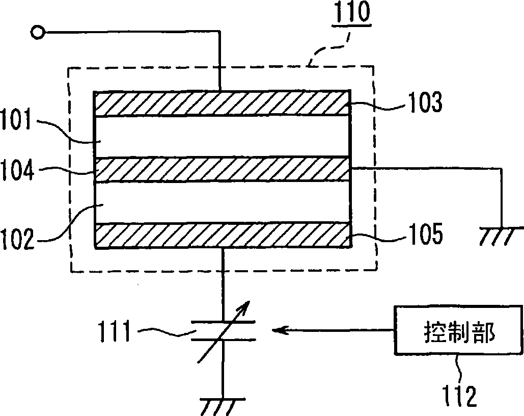
[0116] Figure 9 It is a block diagram of a frequency variable acoustic thin film resonator according to Embodiment 2 of the present invention. The difference between this embodiment and Embodiment 1 is that instead of Figure 1A The load 108 shown is provided with a switching element 201 and a control unit 202 for controlling the switching element 201 is provided.

[0117] In addition, the structure and operation of the acoustic thin film resonator 200 are the same as those of the acoustic thin film resonator 100 of Embodiment 1, and the same reference numerals are attached to the same elements, and repeated descriptions are omitted.

[0118] In the frequency variable acoustic thin film resonator of the present embodiment configured as described above, the following features are exhibited by providing the switching element 201 .

[0119] First, by using the switching element 201 operable in the open state and the short-circuit state as the load, changing the load according ...

Embodiment approach 3

[0122] The reference indicates the characteristic change with respect to the film thickness change of the piezoelectric body and the electrode Figure 11 , and the frequency-variable acoustic thin film resonator according to Embodiment 3 will be described. The frequency-variable acoustic thin film resonator in this embodiment has substantially the same Figure 1A The same structure is shown in which the first piezoelectric body and the second piezoelectric body are stacked.

[0123] Figure 11 shows the structure of the frequency-variable acoustic thin film resonator shown in Embodiment 1 ( Figure 1A ), the thickness is fixed using Mo as the electrode material, AlN is used as the piezoelectric material, and the characteristics obtained by changing the film thicknesses of the first piezoelectric body 101 and the second piezoelectric body 102 are calculated.

[0124] exist Figure 11 In the graph, the horizontal axis represents the film thickness ratio P / T of the film thick...


PUM


Abstract

An acoustic film resonator comprises a first piezoelectric film (101); a pair of primary electrodes (103,104) that are formed on the first piezoelectric film and to which an electric signal is applied; a second piezoelectric film (102) that is disposed such that oscillation occurring in the first piezoelectric film propagates to the second piezoelectric film; a pair of secondary electrodes (104,105) that are formed on the second piezoelectric film and that outputs an electric signal; a load (108) connected between the secondary electrodes; and a control part (109) that controls the value of the load. Thus, an acoustic film resonating element is configured wherein an electric signal from the primary electrodes is outputted from the secondary electrodes through a piezoelectric effect and wherein the resonance frequency and the antiresonance frequency can be varied by controlling the value of the load. Both the resonance frequency and the antiresonance frequency can be varied at the same time without degrading the resonance characteristic.

Description

technical field [0001] The present invention relates to a frequency variable acoustic thin film resonator capable of suppressing the generation of spurious and a filter using the frequency variable acoustic thin film resonator. Background technique [0002] Components built into electronic devices such as portable devices are increasingly required to be smaller and lighter. For example, filters used in portable devices are required to be miniaturized, and are required to have variable center frequencies and frequency bands. As one of filters satisfying these requirements, a filter using an acoustic thin film resonator is known (see Patent Documents 1 and 2). [0003] First, refer to Figure 17 A conventional acoustic thin film resonator described in Patent Document 1 will be described. [0004] Figure 17 Shows the cross-sectional structure of an acoustic thin film resonator. This acoustic thin film resonator has a structure in which a piezoelectric body 2 and semiconduct...

Claims


Application Information

Patent Timeline
IPC IPC(8): H03H9/17H03H9/02H03H9/54H01L41/09
CPCH03H9/564H03H9/132H03H9/605H03H9/587H03H9/585H03H9/542H03H2009/02204
Inventor 中塚宏山川岳彦大西庆治
Owner PANASONIC CORP
Why Eureka
Try Eureka