Inhalation device for electric dust collector

A suction device and vacuum cleaner technology, applied in the direction of vacuum cleaners, suction nozzles, applications, etc., to achieve the effect of miniaturization and compact configuration

Inactive Publication Date: 2009-08-12
SANYO ELECTRIC CO LTD
View PDF1 Cites 4 Cited by
  • Summary
  • Abstract
  • Description
  • Claims
  • Application Information

AI Technical Summary

Problems solved by technology

[0007] In the suction body described in Patent Document 1, it is necessary to secure a space on the upstream side of the suction joint for the confluence of the external air flowing into the turbine chamber from the suction port and the air and dust sucked into the brush chamber from the suction port. Therefore, there is a concern of increasing the size of the suction port

Method used


Image

  • Inhalation device for electric dust collector
  • Inhalation device for electric dust collector
  • Inhalation device for electric dust collector

Examples


Embodiment Construction

[0031] Embodiments of the present invention will be specifically described below with reference to the drawings.

[0032] 1. The overall composition of the electric vacuum cleaner

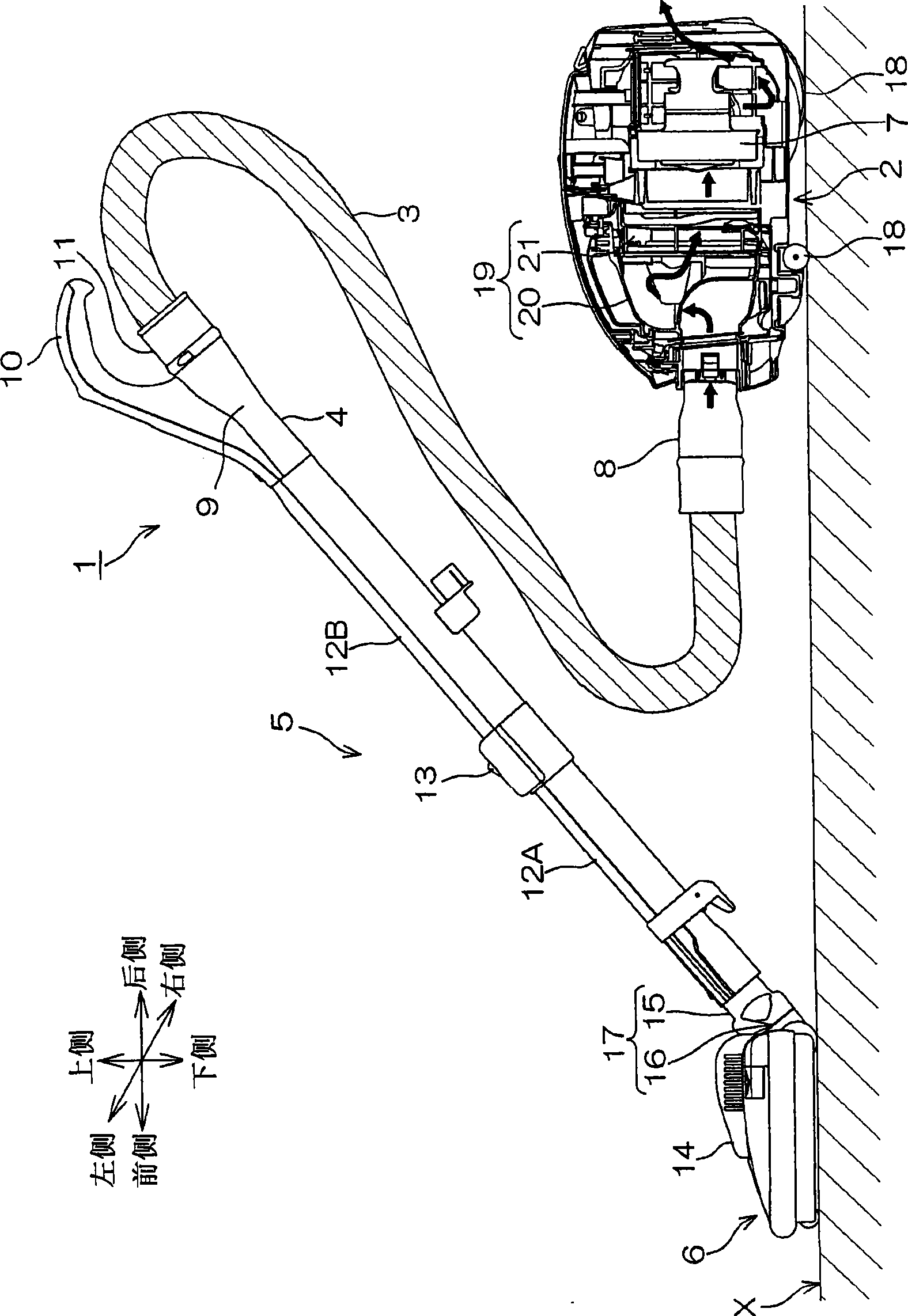
[0033] figure 1 It is a right side view of vacuum cleaner 1 including suction device 6 for vacuum cleaner according to one embodiment of the present invention. and, in figure 1 In , the vacuum cleaner main body 2 is shown in cross section.

[0034] In the following, for the convenience of explanation, in figure 1 In the description, the left side is the front (front), the right side is the rear (rear), the near side (the paper faces outward) is the right, and the back side (the paper faces inward) is the left. When describing the components or the inhalation device 6 , the directions will be described by distinguishing between front and rear, left and right, and up and down. Also, the left-right direction is synonymous with the width direction.

[0035] refer to figure 1 , the vacuum cleaner...


PUM


Abstract

The invention provides an inhaler device for electric vacuum cleaner, which comprises a turbine capable of making the rotary brush rotate, and is capable of miniature. In the inhaler device, the dust containing air (including dust or the like) flows into a bent pipe from a connection portion after being inhaled into the housing from the inhaler port and flowing through a main inhalation wind passage. Moreover, the turbine rotates under the action the air flowing through the wind passage for the turbine, and making the rotary brush rotate. In the housing, the air flowing through the wind passage for the turbine converges with the dust or the like flowing through a main inhalation wind passage at the inner side of the connection portion of the bent pipe. Therefore, because that space can be saved by converging the dust or the like flowing through a main inhalation wind passage with the air flowing through the wind passage for the turbine, miniature of the housing and the inhaler device can be realized.

Description

technical field [0001] The invention relates to a suction device for an electric vacuum cleaner, in particular to a suction device which is installed on the electric vacuum cleaner for use, sucks the dust on the surface to be cleaned and sends it to the main body of the electric vacuum cleaner. Background technique [0002] In an existing suction device for electric vacuum cleaners, a rotating brush is arranged at a suction port formed on the surface opposite to the surface to be cleaned in the casing, and by rotating the rotating brush, the dust on the surface to be cleaned is collected, and the dust on the surface to be cleaned is collected. The collected dust is sent to the side of the main body of the electric vacuum cleaner from the suction port, so as to clean the surface to be cleaned. [0003] In addition, there is known a suction device (refer to Patent Document 1) which has a built-in turbine, and the turbine is rotated by using the air flow sucked in, and the rota...

Claims


Application Information

Patent Timeline
Patent Type & Authority Applications(China)
IPC IPC(8): A47L9/04
CPCA47L9/0416A47L9/0477A47L9/248
Inventor 中井康一
Owner SANYO ELECTRIC CO LTD
Why Eureka
Try Eureka